Check out my first novel, midnight's simulacra!
Dankdryer: Difference between revisions
(→Croom) |
|||
| (One intermediate revision by the same user not shown) | |||
| Line 11: | Line 11: | ||
* LM35 thermostat (up to 150C) | * LM35 thermostat (up to 150C) | ||
* 110V 230C 3.03" x 2.44" ceramic heating element (230C) | * 110V 230C 3.03" x 2.44" ceramic heating element (230C) | ||
* 150C NC thermocouple | * 150C NC thermocouple | ||
* [[Noctua]] NF-A8 80mm 12V fan | * [[Noctua]] NF-A8 80mm 12V fan | ||
* Chamber material: Bambu PAHT-CF (225C) | |||
The hotbox mates to the croom via four corners using M5x40mm screws. It has a 80mm fan for exhaust opposite the heater. This is not 80x80mm² (6400mm²) of exhaust, but rather π40² (~5026.5mm²), since the fan is circular. We thus want ~5026.5mm² of vents in the floor. The heater is wired to the AC and to the thermocouple, which will open (killing the circuit) if the chamber reaches 150C. | The hotbox mates to the croom via four corners using M5x40mm screws. It has a 80mm fan for exhaust opposite the heater. This is not 80x80mm² (6400mm²) of exhaust, but rather π40² (~5026.5mm²), since the fan is circular. We thus want ~5026.5mm² of vents in the floor. The heater is wired to the AC and to the thermocouple, which will open (killing the circuit) if the chamber reaches 150C. | ||
| Line 26: | Line 26: | ||
* TB6612FNG motor controller | * TB6612FNG motor controller | ||
* Chamber material: Polymaker polycarbonate clear (260C) | * Chamber material: Polymaker polycarbonate clear (260C) | ||
The AC adapter is mounted along the side opposite the intake fan. The motor is placed on its stand, secured via six short M3 screws into the front, and wired to one of the TB6612FNG's outputs. One of the AC adapter's outputs is sent to the LMS2596, which takes it to 5V and is wired via USB-C to the ESP32-S3 (this allows us to drive the MCU via external USB for testing). The other 12V output is wired to the perfboard, where it is sent to the two fan plugs and the TB6612FNG. The exhaust and intake fans are both connected to the fan plugs. The MCU is connected to the TB6612FNG and the HX711. The HX711 is connected to the load cell, which is mounted into the chamber. The lower coupling is mounted to the top of the load cell. | |||
The worm gear is placed on the end of the rotor. The shaft is inserted into a 608 bearing. The gear is pushed down the shaft. The assembled shaft is placed into the lower coupling. The hotbox can now be attached to the croom. Finally, the spool platform is placed on the shaft. | |||
[[CATEGORY: Projects]] | [[CATEGORY: Projects]] | ||
[[CATEGORY: 3D Printing]] | [[CATEGORY: 3D Printing]] | ||
Latest revision as of 13:43, 25 September 2024
Some engineering filaments specify drying at temperatures up to 140C. Standard filament dryers can't approach this temperature (most peak at 70--80C). How to construct one that can handle it?
We need materials and electronics which can operate in such an environment. Ideally, we'll keep most of the electronics out of the heated chamber, but it'll likely be quite warm immediately outside as well. This seems possible for everything but our sensors, which must necessarily be within the chamber. We'll need a thermostat, and might want a humidity sensor. We'll also have a load cell to weigh the spool/chamber, and thus let us know how much water has been evaporated. I haven't been able to find a humidity sensor rated above 100C, so that's a nonstarter. We'll want to put the thermostat on lengths of wire.
We'll drive the ceramic heating element via AC, as it wants significant wattage.
Filament-wise, the hot chamber, heat shield, and central column will be printed in Bambu PAHT-CF, while the bottom chamber will be printed in Polymaker polycarbonate.
Hotbox

- LM35 thermostat (up to 150C)
- 110V 230C 3.03" x 2.44" ceramic heating element (230C)
- 150C NC thermocouple
- Noctua NF-A8 80mm 12V fan
- Chamber material: Bambu PAHT-CF (225C)
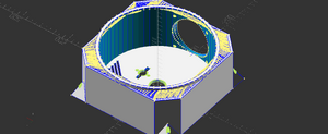
The hotbox mates to the croom via four corners using M5x40mm screws. It has a 80mm fan for exhaust opposite the heater. This is not 80x80mm² (6400mm²) of exhaust, but rather π40² (~5026.5mm²), since the fan is circular. We thus want ~5026.5mm² of vents in the floor. The heater is wired to the AC and to the thermocouple, which will open (killing the circuit) if the chamber reaches 150C.
Croom

- Geartisan 12V DC 5RPM motor
- HX711 + 5kg axial load cell
- ESP32-S3-WROOM
- AC -> DC 12V adapter
- LMS2596 buck converter
- TB6612FNG motor controller
- Chamber material: Polymaker polycarbonate clear (260C)
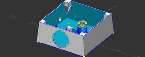
The AC adapter is mounted along the side opposite the intake fan. The motor is placed on its stand, secured via six short M3 screws into the front, and wired to one of the TB6612FNG's outputs. One of the AC adapter's outputs is sent to the LMS2596, which takes it to 5V and is wired via USB-C to the ESP32-S3 (this allows us to drive the MCU via external USB for testing). The other 12V output is wired to the perfboard, where it is sent to the two fan plugs and the TB6612FNG. The exhaust and intake fans are both connected to the fan plugs. The MCU is connected to the TB6612FNG and the HX711. The HX711 is connected to the load cell, which is mounted into the chamber. The lower coupling is mounted to the top of the load cell.
The worm gear is placed on the end of the rotor. The shaft is inserted into a 608 bearing. The gear is pushed down the shaft. The assembled shaft is placed into the lower coupling. The hotbox can now be attached to the croom. Finally, the spool platform is placed on the shaft.