Check out my first novel, midnight's simulacra!
Dankdryer improvements: Difference between revisions
Jump to navigation
Jump to search
| (18 intermediate revisions by the same user not shown) | |||
| Line 1: | Line 1: | ||
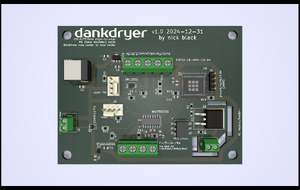
In an [[Dankdryer|earlier article]], I designed and constructed a high-temperature [[Filaments|filament]] dryer. Before I was even done putting together the first design, I was thinking of improvements for reliability, efficiency, cost, and ease of assembly. I've put some of them into effect, and the results are most pleasing. | [[File:Dankdryer.png|thumb|right|The Dankdryer PCB]] | ||
In an [[Dankdryer|earlier article]], I designed and constructed a high-temperature [[Filaments|filament]] dryer. Before I was even done putting together the first design, I was thinking of improvements for reliability, efficiency, cost, and ease of assembly. I've put some of them into effect, and the results are most pleasing. Most importantly, I designed a PCB to replace the perfboard and through-hole mess of the original. Like the rest of the project, the KiCad schematics and PCB design are open source. | |||
==Problems with v1== | |||
* It was very difficult to keep the spool level between the impact of the worm gear and the load cell structure. | |||
* The motor was loud. | |||
* It was difficult to print the bottom chamber without corner warping, which further threw off the spool leveling. | |||
* Lack of a standard power hookup required mutilating three-prong cables. | |||
==Models== | ==Models== | ||
* Cut the bottom chamber down mercilessly to save mass, aiming to get the sum of both chambers below 500g using my recommended settings. Haven't reached it yet, but we're close. | * Cut the bottom chamber down mercilessly to save mass, aiming to get the sum of both chambers below 500g using my recommended settings. Haven't reached it yet, but we're close. | ||
* | * Completely changed the motor mount. It's now vertical, and sits atop the load cell. I didn't want its weight in the load cell's measurement, but it wasn't at all worth the added complexity of an orthogonal motor (worm gear, etc.). Things work **much** better now -- you can put a level atop the spool, and watch it rotate serenely for hours. Eliminated the air shield; it didn't prove necessary, and significantly increased print time. | ||
* Added a hole for an RP-SMA antenna, and a hole for a NEMA plug + rocker switch. | |||
* Added helical forms to the top and the hot chamber, so they screw together. | |||
* | |||
* | |||
==Electronics== | ==Electronics== | ||
* Let's toss the TB6612FNG motor controller. We only need one direction of rotation, so we control the motor with an | * I added a Hall sensor to the roof, and with a magnet on the spool platform, we can now detect spool rotations. More importantly, we can detect a failure to rotate, probably indicative of obstruction or even melting. This is important, because the spool will otherwise heat asymmetrically. | ||
* Let's toss the TB6612FNG motor controller. We only need one direction of rotation, so we control the motor with an N-channel MOSFET, a 330 and 1.62K resistor, and a [https://www.vishay.com/docs/88525/1n5817.pdf 1N5817] Schottky diode. The n-FET goes on the ground side of the motor, and the diode runs in parallel with the load (i.e. is connected to the motor's two pins). The resistor pulls down the gate lead. This eliminates four net wires (AIN1, AIN2, STBY, AO2, APWM go away; we add GATE) while adding two resistors. | |||
* The LM35 is operating in a nasty thermal environment, and on about ten centimeters of poorly-shielded AWG22. Let's give it some bigger boxing gloves. Put a 0. | * The LM35 is operating in a nasty thermal environment, and on about ten centimeters of poorly-shielded AWG22. Let's give it some bigger boxing gloves. Put a 0.01µF bypass capacitor across its power and ground leads. Put a 75Ω resistor and a 0.22µF capacitor in series between the signal and the ground. These recommendations come directly from the [https://www.ti.com/lit/ds/symlink/lm35.pdf datasheet]: | ||
[[File:LM35-circuit.png]] | [[File:LM35-circuit.png]] | ||
===PCB considerations=== | ===PCB considerations=== | ||
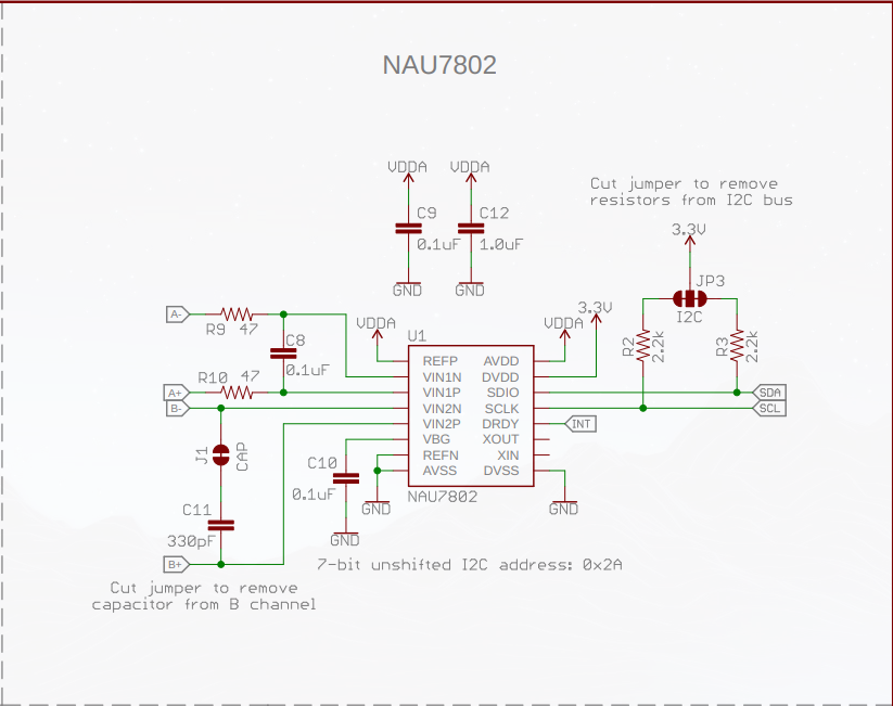
* We're ditching the Sparkfun NAU7802 breakout board, so we'll need add 2.2kΩ pullups on both I2C lines, 0.1µF and 1µF capacitors on VDDA, and 47Ω resistors on VNN1N and VNN1P with a 0.1µF bypass capacitor across them. See the [https://cdn.sparkfun.com/assets/6/a/5/9/d/Qwiic_Scale.pdf schematic]: | * We're ditching the Sparkfun NAU7802 breakout board, so we'll need add 2.2kΩ pullups on both I2C lines, 0.1µF and 1µF capacitors on VDDA, and 47Ω resistors on VNN1N and VNN1P with a 0.1µF bypass capacitor across them. See the [https://cdn.sparkfun.com/assets/6/a/5/9/d/Qwiic_Scale.pdf schematic]: | ||
[[File:SparkFun-NAU7802.png]] | [[File:SparkFun-NAU7802.png]] | ||
* The first version took in 120VAC, 12VDC, and 5VDC (i.e. there was a discrete buck converter from 12 → 5VDC). Let's build that circuit into the PCB, so we're only working with 120VAC and 12VDC (the native output of the AC adapter) inputs. At the same time, let's move the ESP32 over to 3.3V input (at least when we're not powering it with external USB), so we don't exercise its low-efficiency voltage regulator. We'll still want 5V to the LM35 and the HX711's AVDD. Since these are both precision analog devices requiring very small currents, we'll use a voltage regulator from 12->5; this ought be less noisy than a switching transformer. | |||
==Thoughts== | |||
* Rather than mounting the RC522 directly onto the bottom of the top chamber, we print a short mount for it (building the mount into the hotbox would make it very difficult to print). This reduces the heat directly transferred to the RC522, without adding new connectors. The necessary screw holes into the bottom of the chamber already exist. | |||
* I cut out chunks from the eight "fat corners" of the hotbox. I'd like to make these siting areas for dessicants. This <i>added</i> weight, presumably due to more walls vs sparse infill, so I changed it back. | |||
* I experimented with adding a kinda inverted eggholder (actually just a bunch of inverted frustra) to the underside of the bottom chamber, in the hope of eliminating warping. It didn't really pan out (a good number detached from the build plate), and you need defeat warping for the top chamber anyway, so I removed them. | |||
* I'd love to get rid of the internal AC, but the heater maxes out at 4.5A of 120VAC. That's 45A of 12VDC, and now you're talking a (fairly large) power supply running close to $30. | |||
* Maybe we should replace the hot chamber thermometer with a K-type thermocouple and the necessary PCB electronics/connector? This looks quite expensive; if we don't need it, let's not. | |||
Latest revision as of 12:13, 31 December 2024

In an earlier article, I designed and constructed a high-temperature filament dryer. Before I was even done putting together the first design, I was thinking of improvements for reliability, efficiency, cost, and ease of assembly. I've put some of them into effect, and the results are most pleasing. Most importantly, I designed a PCB to replace the perfboard and through-hole mess of the original. Like the rest of the project, the KiCad schematics and PCB design are open source.
Problems with v1
- It was very difficult to keep the spool level between the impact of the worm gear and the load cell structure.
- The motor was loud.
- It was difficult to print the bottom chamber without corner warping, which further threw off the spool leveling.
- Lack of a standard power hookup required mutilating three-prong cables.
Models
- Cut the bottom chamber down mercilessly to save mass, aiming to get the sum of both chambers below 500g using my recommended settings. Haven't reached it yet, but we're close.
- Completely changed the motor mount. It's now vertical, and sits atop the load cell. I didn't want its weight in the load cell's measurement, but it wasn't at all worth the added complexity of an orthogonal motor (worm gear, etc.). Things work **much** better now -- you can put a level atop the spool, and watch it rotate serenely for hours. Eliminated the air shield; it didn't prove necessary, and significantly increased print time.
- Added a hole for an RP-SMA antenna, and a hole for a NEMA plug + rocker switch.
- Added helical forms to the top and the hot chamber, so they screw together.
Electronics
- I added a Hall sensor to the roof, and with a magnet on the spool platform, we can now detect spool rotations. More importantly, we can detect a failure to rotate, probably indicative of obstruction or even melting. This is important, because the spool will otherwise heat asymmetrically.
- Let's toss the TB6612FNG motor controller. We only need one direction of rotation, so we control the motor with an N-channel MOSFET, a 330 and 1.62K resistor, and a 1N5817 Schottky diode. The n-FET goes on the ground side of the motor, and the diode runs in parallel with the load (i.e. is connected to the motor's two pins). The resistor pulls down the gate lead. This eliminates four net wires (AIN1, AIN2, STBY, AO2, APWM go away; we add GATE) while adding two resistors.
- The LM35 is operating in a nasty thermal environment, and on about ten centimeters of poorly-shielded AWG22. Let's give it some bigger boxing gloves. Put a 0.01µF bypass capacitor across its power and ground leads. Put a 75Ω resistor and a 0.22µF capacitor in series between the signal and the ground. These recommendations come directly from the datasheet:
PCB considerations
- We're ditching the Sparkfun NAU7802 breakout board, so we'll need add 2.2kΩ pullups on both I2C lines, 0.1µF and 1µF capacitors on VDDA, and 47Ω resistors on VNN1N and VNN1P with a 0.1µF bypass capacitor across them. See the schematic:
- The first version took in 120VAC, 12VDC, and 5VDC (i.e. there was a discrete buck converter from 12 → 5VDC). Let's build that circuit into the PCB, so we're only working with 120VAC and 12VDC (the native output of the AC adapter) inputs. At the same time, let's move the ESP32 over to 3.3V input (at least when we're not powering it with external USB), so we don't exercise its low-efficiency voltage regulator. We'll still want 5V to the LM35 and the HX711's AVDD. Since these are both precision analog devices requiring very small currents, we'll use a voltage regulator from 12->5; this ought be less noisy than a switching transformer.
Thoughts
- Rather than mounting the RC522 directly onto the bottom of the top chamber, we print a short mount for it (building the mount into the hotbox would make it very difficult to print). This reduces the heat directly transferred to the RC522, without adding new connectors. The necessary screw holes into the bottom of the chamber already exist.
- I cut out chunks from the eight "fat corners" of the hotbox. I'd like to make these siting areas for dessicants. This added weight, presumably due to more walls vs sparse infill, so I changed it back.
- I experimented with adding a kinda inverted eggholder (actually just a bunch of inverted frustra) to the underside of the bottom chamber, in the hope of eliminating warping. It didn't really pan out (a good number detached from the build plate), and you need defeat warping for the top chamber anyway, so I removed them.
- I'd love to get rid of the internal AC, but the heater maxes out at 4.5A of 120VAC. That's 45A of 12VDC, and now you're talking a (fairly large) power supply running close to $30.
- Maybe we should replace the hot chamber thermometer with a K-type thermocouple and the necessary PCB electronics/connector? This looks quite expensive; if we don't need it, let's not.

