Check out my first novel, midnight's simulacra!
Three recent physical projects: Difference between revisions
| Line 39: | Line 39: | ||
I'd already [[Waveshare_AMOLED|designed this faceplate]] and the AMOLED+[[Raspberry_Pi|Raspberry Pi]] that sits inside. I added a strip of high-intensity CoB LEDs, as long intended. I reprinted it using black ABS. To power the 12V LEDs, I took a SATA power cable and cut off the female end. I then separated the five cables. Bifurcate the ground wire, and solder a ground + 12V to the LED strip. SATA provides 5V and 12V (and sometimes 3.3V, unnecessary here), so we'll use the 5V to power the Pi+AMOLED (this will provide more amperage than a USB hookup). Bifurcate the 5V and second ground line, and solder one pair to each of two USB-µA plugs. Thread the LED strip through the faceplate in front of the OLED. | I'd already [[Waveshare_AMOLED|designed this faceplate]] and the AMOLED+[[Raspberry_Pi|Raspberry Pi]] that sits inside. I added a strip of high-intensity CoB LEDs, as long intended. I reprinted it using black ABS. To power the 12V LEDs, I took a SATA power cable and cut off the female end. I then separated the five cables. Bifurcate the ground wire, and solder a ground + 12V to the LED strip. SATA provides 5V and 12V (and sometimes 3.3V, unnecessary here), so we'll use the 5V to power the Pi+AMOLED (this will provide more amperage than a USB hookup). Bifurcate the 5V and second ground line, and solder one pair to each of two USB-µA plugs. Thread the LED strip through the faceplate in front of the OLED. | ||
[[File:Frontplate-leds.jpg|frame]] | [[File:Frontplate-leds.jpg|frame]] | ||
Beautiful! Tremendous! | Beautiful! Tremendous! This occupies two 5.25" bays. | ||
==Filter tower== | ==Filter tower== | ||
Revision as of 05:22, 22 June 2024
dankblog! 2024-06-22, 2334 EST, at the danktower
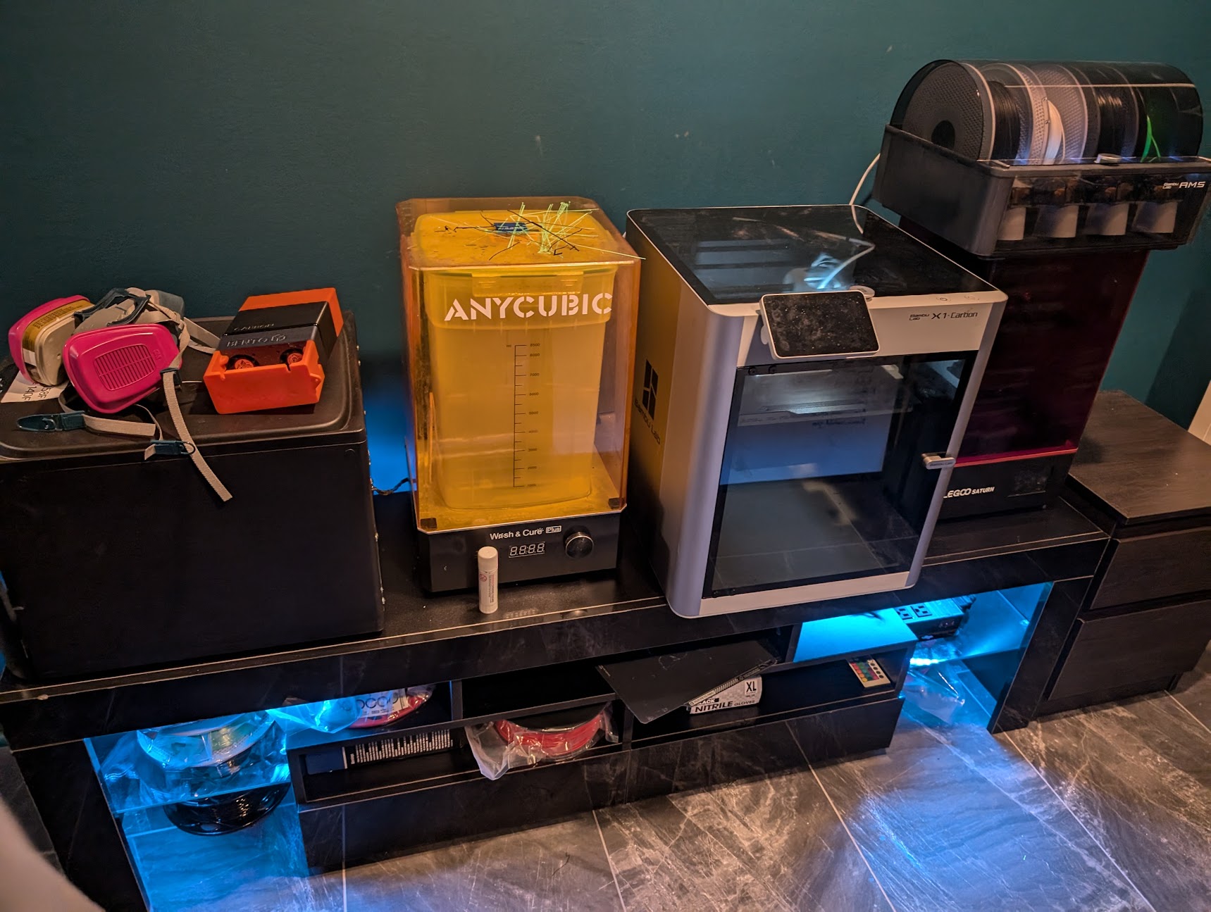
I recently got my Bambu X1 Carbon working again, after being offline for almost two years. Doing so motivated me to knock out some projects I'd been contemplating.
Air contaminant detector
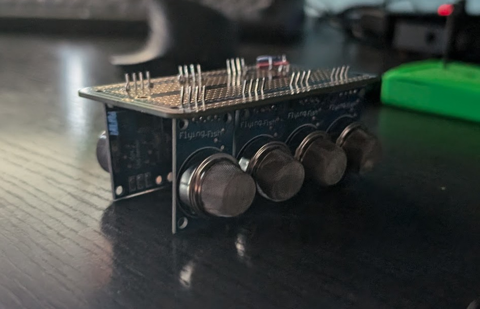
I wanted a CO detector, but figured I might as well detect everything I could. A sack of nine MQ-series detectors runs about $15 on Amazon. This gets you:
- MQ-2: chemiresistor: flammable gas/smoke
- MQ-3: SnO₂ (tin/stannic oxide): alcohol, benzene, methane, hexane, LPG, CO
- MQ-4: SnO₂ + Al₂O₃ (aluminum oxide): methane
- MQ-5: gas
- MQ-6: isobutane, propane, LPG
- MQ-7: CO
- MQ-8: H₂
- MQ-9: LPG, CO, methane
- MQ-135: ammonia, sulfur, benzene, CO₂
Each runs on 5V, and exposes four pins: V, GND, analog out, and digital out. The digital out is controlled by a dialed-in threshold. I usually employ ESP32s in new designs, but the 5V suggests an Arduino or even Raspberry Pi (we'd otherwise need employ voltage dividers on each of the analog inputs, or use a level shifter, to reduce them to 3.3V). An Arduino Uno only offers 6 analog inputs, but a Mega2560 can handle nine with no problems. The 16MHz ATmega2560 CPU ought provide more than enough computational power; there's no need to reach for a Pi.
The first problem we encounter is that these sensors want hundreds of milliamps, but the 5V power pins on the Mega offer no more than 200mA per. If we're powering the Mega via its USB connection, we're capped at 500mA total. So no matter how we power the Mega, we're going to need external power for the sensors. Fair enough. I had a 3A 5V AC adapter with USB-µA output lying around. Its 15W ought be sufficient to handle everything. So first I took out a ElectroCookie 88.9mm x 52.1mm perfboard and verified that I could fit eight sensors onto it. This perfboard, like a breadboard, has two vertical channels on each side for V and GND, and the horizontal channels have preexisting traces—very convenient!
Solder each pin to the board (32 solder points total). I'm not the world's best at soldering, so whenever I do this, I break out my multimeter and ensure no rows are unexpectedly connected, and that all my pins are connected as desired. To do this, it's sufficient to put one probe on the pin, and another probe on the horizontal channel in which the pin is inserted. A tone means you're good (the pin is properly soldered to the board). Then move the first probe to the two adjacent channels. A tone now is no good (solder has joined two rows). Remember, if you solder together a V and G, that's a short, and you're likely going to blow something up.
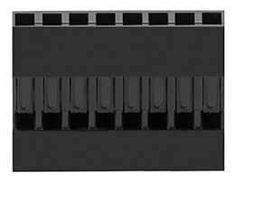
Now, add power and ground: on each sensor, add a wire from the ground channel to the vertical ground, and a wire from the V channel to the vertical V. Solder these 32 points, and test everything again. You ought be able to lift the perfboard without any of the sensors or wires moving. Finally, cut eight wires, and strip the ends. Solder them to the analog channels (8 points total). Take the eight ends, insert them into male crimp pins, and crimp. Insert these into an 1x8P 2.54mm Dupont crimp housing. Add a row of eight 2.54mm pitch male headers. This will be going into the column of eight analog inputs on our Mega.
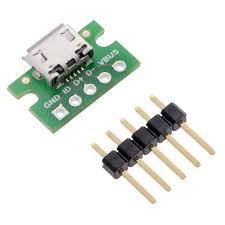
We need to power all this. Take a USB-µA breakout board and add it to the top. Solder all five pins. Connect the 5V and G channels to the appropriate vertical channels with two wires; solder the wires. Now connect the two sets of vertical channels with two wires, and solder them. You now ought have connectivity across the two V channels and the two ground channels (but not between them)! Go ahead and test with power now. Hook the AC adapter up via USB; you ought be able to measure 5V across the V and G channels with your multimeter. Do not try to power this with a computer's USB ports; they're typically capped to 0.5A or 0.9A, and the sensors will draw more than this in aggregate.
Finally, we'll want to add WiFi to this setup (the Mega has neither Ethernet nor WiFi built in). Get an ESP8266 ESP-01S WiFi module along with a 3.3V-5V adapter. Without the adapter, you'll need to level shift the 5V UART TX signal from the Mega, and add some resistors on the power hookup. This $0.50 adapter handles that for you. Stick it in the top, and solder all four points. Obviously, use unoccupied horizontal channels. Two wires for V and G, four solder points, you know the drill. We'll also need two longer wires for RX and TX. Solder them in, and prepare a 1x2P Dupont hookup. These will be going into RX3 and TX3 on the Mega.
We'll want some kind of housing to keep these sensors and plugs in place, but we don't want to block the air intakes. I designed one in a few minutes using OpenSCAD. This results in a cuboid with two channels for the sensors, and a through for the plugs. I printed it with black ABS. Thread the plugs through, and then ensure all eight sensors are securely in their channels. If you'd like, add some superglue to these channels. You ought now have a secure sensor array.
That's the hard part. Now, print a case for the Mega; I liked this one from Thingiverse. I used PLA here, mostly because I needed to print supports for the topside, and I didn't have any HIPS breakaway filament. PVA isn't suitable for ABS; the temperature mismatch will fuck up adhesion.
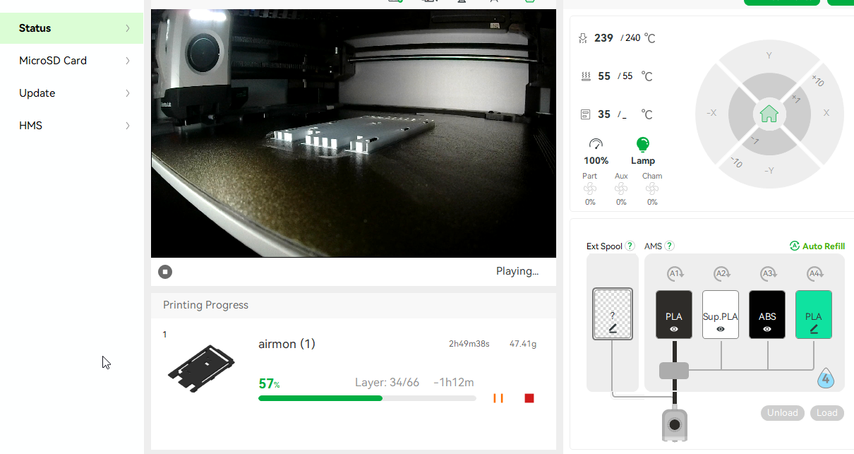
With our case in hand, insert the Mega2560 and close the case. Solder two wires from the V and G channels of the perfboard, and take these into a USB-B screw terminal (the Arduino wants 7V from a direct line in, but only 5V from a USB hookup). Insert the terminal into the Mega. Insert the 1x2P plug into TX3+RX3, and the 1x8P plug into A0..A7. You ought now power on the Mega when you attach the USB to the top plug. Congratulations! The Arduino code is trivial; just poll the eight analog inputs, and stream the results over WiFi using MQTT or whatever you'd like.
Case faceplate with OLED display
I'd already designed this faceplate and the AMOLED+Raspberry Pi that sits inside. I added a strip of high-intensity CoB LEDs, as long intended. I reprinted it using black ABS. To power the 12V LEDs, I took a SATA power cable and cut off the female end. I then separated the five cables. Bifurcate the ground wire, and solder a ground + 12V to the LED strip. SATA provides 5V and 12V (and sometimes 3.3V, unnecessary here), so we'll use the 5V to power the Pi+AMOLED (this will provide more amperage than a USB hookup). Bifurcate the 5V and second ground line, and solder one pair to each of two USB-µA plugs. Thread the LED strip through the faceplate in front of the OLED.
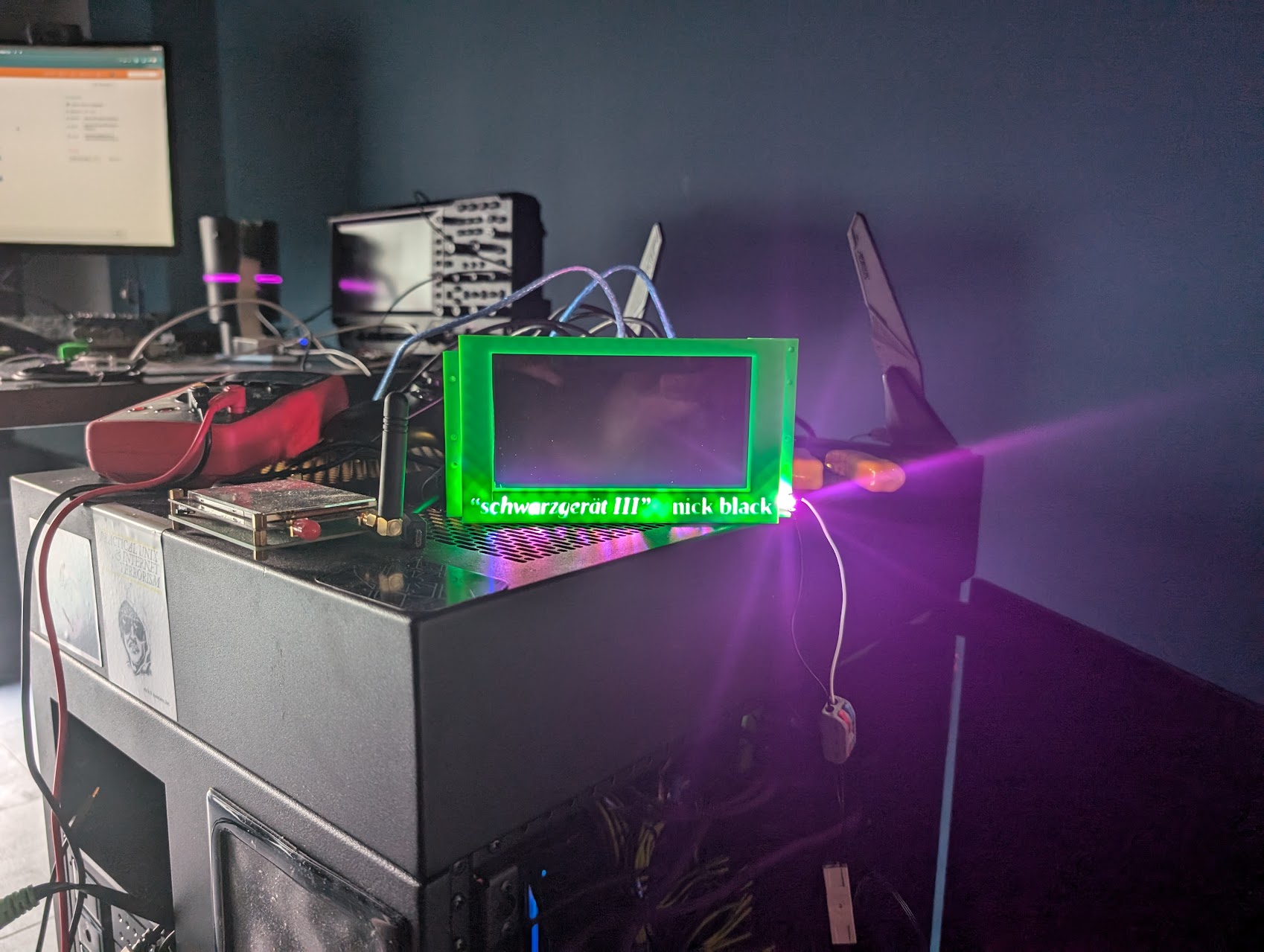
Beautiful! Tremendous! This occupies two 5.25" bays.
Filter tower
previously: "The beginning of the end of iptables" 2024-04-19
