Check out my first novel, midnight's simulacra!
CODI6: Difference between revisions
From dankwiki
No edit summary |
|||
| Line 14: | Line 14: | ||
I'm not sure which, if any, PWM receptacles passes on a tach signal for return. | I'm not sure which, if any, PWM receptacles passes on a tach signal for return. | ||
==Pin to functional element mapping== | |||
(bottom is <i>opposite</i> the USB/power jack) | |||
* Pin 3 maps to the bottom, leftmost ARGB hookup | |||
* Pin 6 maps to the bottom, rightmost ARGB hookup | |||
[[CATEGORY: Hardware]] | [[CATEGORY: Hardware]] | ||
Revision as of 08:07, 1 October 2022

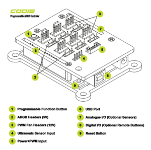
An ARGB/PWM controller from Gelid, based around an Arduino Uno clone. Each 5V channel can put out 4A (though the SATA power connector can only carry 4.5A total of 5V power in...).
What exactly is https://github.com/notabucketofspam/ARGB?
The shield
The shield has six rows of interfaces:
- A 5-pin receptacle coupled to a custom cable (this cable has a 4-pin PWM (fan) plug and a male SATA power plug), and a 4-pin hookup for an ultrasonic sensor.
- 3x 5V 3-pin ARGB receptacles
- 3x 12V 4-pin PWM receptacles
- 3x 5V 3-pin ARGB receptacles
- 3x 12V 4-pin PWM receptacles
- a function button
I'm not sure which, if any, PWM receptacles passes on a tach signal for return.
Pin to functional element mapping
(bottom is opposite the USB/power jack)
- Pin 3 maps to the bottom, leftmost ARGB hookup
- Pin 6 maps to the bottom, rightmost ARGB hookup