| [ Team LiB ] |


|
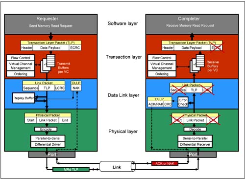
Example of a Non-Posted Memory Read TransactionLet us put our knowledge so far to describe the set of events that take place from the time a requester device initiates a memory read request, until it obtains the requested data from a completer device. Given that such a transaction is a non-posted transaction, there are two phases to the read process. The first phase is the transmission of a memory read request TLP from requester to completer. The second phase is the reception of a completion with data from the completer. Memory Read Request PhaseRefer to Figure 2-31. The requester Device Core or Software Layer sends the following information to the Transaction Layer: Figure 2-31. Memory Read Request Phase
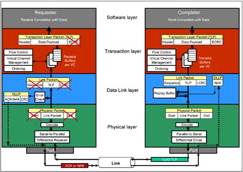
32-bit or 64-bit memory address, transaction type of memory read request, amount of data to read calculated in doublewords, traffic class if other than TC0, byte enables, attributes to indicate if 'relaxed ordering' and 'no snoop' attribute bits should be set or clear. The Transaction layer uses this information to build a MRd TLP. The exact TLP packet format is described in a later chapter. A 3 DW or 4 DW header is created depending on address size (32-bit or 64-bit). In addition, the Transaction Layer adds its requester ID (bus#, device#, function#) and an 8-bit tag to the header. It sets the TD (transaction digest present) bit in the TLP header if a 32-bit End-to-End CRC is added to the tail portion of the TLP. The TLP does not have a data payload. The TLP is placed in the appropriate virtual channel buffer ready for transmission. The flow control logic confirms there are sufficient "credits" available (obtained from the completer device) for the virtual channel associated with the traffic class used. Only then the memory read request TLP is sent to the Data Link Layer. The Data Link Layer adds a 12-bit sequence ID and a 32-bit LCRC which is calculated based on the entire packet. A copy of the TLP with sequence ID and LCRC is stored in the replay buffer. This packet is forwarded to the Physical Layer which tags on a Start symbol and an End symbol to the packet. The packet is byte striped across the available Lanes, scrambled and 10 bit encoded. Finally the packet is converted to a serial bit stream on all Lanes and transmitted differentially across the Link to the neighbor completer device. The completer converts the incoming serial bit stream back to 10b symbols while assembling the packet in an elastic buffer. The 10b symbols are converted back to bytes and the bytes from all Lanes are de-scrambled and un-striped. The Start and End symbols are detected and removed. The resultant TLP is sent to the Data Link Layer. The completer Data Link Layer checks for LCRC errors in the received TLP and checks the Sequence ID for missing or out-of-sequence TLPs. Assume no error. The Data Link Layer creates an ACK DLLP which contains the same sequence ID as contained in the memory read request TLP received. A 16-bit CRC is added to the ACK DLLP. The DLLP is sent back to the Physical Layer which transmits the ACK DLLP to the requester. The requester Physical Layer reformulates the ACK DLLP and sends it up to the Data Link Layer which evaluates the sequence ID and compares it with TLPs stored in the replay buffer. The stored memory read request TLP associated with the ACK received is discarded from the replay buffer. If a NAK DLLP was received by the requester instead, it would re-send a copy of the stored memory read request TLP. In the mean time the Data Link Layer of the completer strips the sequence ID and LCRC field from the memory read request TLP and forwards it to the Transaction Layer. The Transaction Layer receives the memory read request TLP in the appropriate virtual channel buffer associated with the TC of the TLP. The Transaction layer checks for ECRC error. It forwards the contents of the header (address, requester ID, memory read transaction type, amount of data requested, traffic class etc.) to the completer Device Core/Software Layer. Completion with Data PhaseRefer to Figure 2-32 on page 99 during the following discussion. To service the memory read request, the completer Device Core/Software Layer sends the following information to the Transaction Layer: Figure 2-32. Completion with Data Phase
Requester ID and Tag copied from the original memory read request, transaction type of completion with data (CplD), requested amount of data with data length field, traffic class if other than TC0, attributes to indicate if 'relaxed ordering' and 'no snoop' bits should be set or clear (these bits are copied from the original memory read request). Finally, a completion status of successful completion (SC) is sent. The Transaction layer uses this information to build a CplD TLP. The exact TLP packet format is described in a later chapter. A 3 DW header is created. In addition, the Transaction Layer adds its own completer ID to the header. The TD (transaction digest present) bit in the TLP header is set if a 32-bit End-to-End CRC is added to the tail portion of the TLP. The TLP includes the data payload. The flow control logic confirms sufficient "credits" are available (obtained from the requester device) for the virtual channel associated with the traffic class used. Only then the CplD TLP is sent to the Data Link Layer. The Data Link Layer adds a 12-bit sequence ID and a 32-bit LCRC which is calculated based on the entire packet. A copy of the TLP with sequence ID and LCRC is stored in the replay buffer. This packet is forwarded to the Physical Layer which tags on a Start symbol and an End symbol to the packet. The packet is byte striped across the available Lanes, scrambled and 10 bit encoded. Finally the CplD packet is converted to a serial bit stream on all Lanes and transmitted differentially across the Link to the neighbor requester device. The requester converts the incoming serial bit stream back to 10b symbols while assembling the packet in an elastic buffer. The 10b symbols are converted back to bytes and the bytes from all Lanes are de-scrambled and un-striped. The Start and End symbols are detected and removed. The resultant TLP is sent to the Data Link Layer. The Data Link Layer checks for LCRC errors in the received CplD TLP and checks the Sequence ID for missing or out-of-sequence TLPs. Assume no error. The Data Link Layer creates an ACK DLLP which contains the same sequence ID as contained in the CplD TLP received. A 16-bit CRC is added to the ACK DLLP. The DLLP is sent back to the Physical Layer which transmits the ACK DLLP to the completer. The completer Physical Layer reformulates the ACK DLLP and sends it up to the Data Link Layer which evaluates the sequence ID and compares it with TLPs stored in the replay buffer. The stored CplD TLP associated with the ACK received is discarded from the replay buffer. If a NAK DLLP was received by the completer instead, it would re-send a copy of the stored CplD TLP. In the mean time, the requester Transaction Layer receives the CplD TLP in the appropriate virtual channel buffer mapped to the TLP TC. The Transaction Layer uses the tag in the header of the CplD TLP to associate the completion with the original request. Transaction layer checks for ECRC error. It forwards the header contents and data payload including the Completion Status to the requester Device Core/Software Layer. Memory read transaction DONE. |
| [ Team LiB ] |
|