| [ Team LiB ] |


|
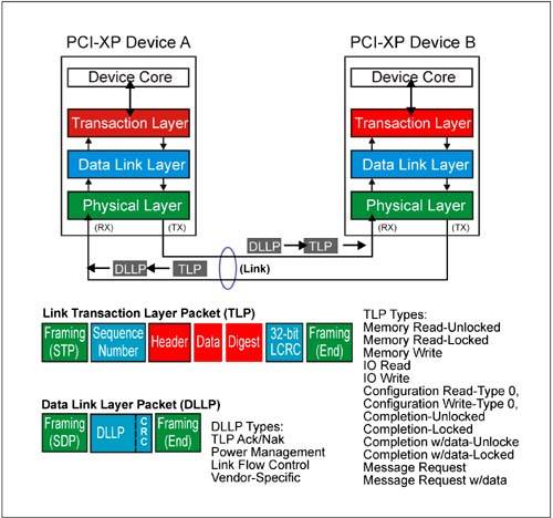
Introduction to the Packet-Based ProtocolThe PCI Express protocol improves upon methods used by earlier busses (e.g. PCI) to exchange data and to signal system events. In addition to supporting basic memory, IO, and configuration read/write transactions, the links eliminate many sideband signals and replaces them with in-band messages. With the exception of the logical idle indication and physical layer Ordered Sets, all information moves across an active PCI Express link in fundamental chunks called packets which are comprised of 10 bit control (K) and data (D) symbols. The two major classes of packets exchanged between two PCI Express devices are high level Transaction Layer Packets (TLPs), and low-level link maintenance packets called Data Link Layer Packets (DLLPs). Collectively, the various TLPs and DLLPs allow two devices to perform memory, IO, and Configuration Space transactions reliably and use messages to initiate power management events, generate interrupts, report errors, etc. Figure 4-1 on page 155 depicts TLPs and DLLPs on a PCI Express link. Figure 4-1. TLP And DLLP Packets
Why Use A Packet-Based Transaction ProtocolThere are some distinct advantages in using a packet-based protocol, especially when it comes to data integrity. Three important aspects of PCI Express packet protocol help promote data integrity during link transmission: Packet Formats Are Well DefinedSome early bus protocols (e.g. PCI) allow transfers of indeterminate (and unlimited) size, making identification of payload boundaries impossible until the end of the transfer. In addition, an early transaction end might be signaled by either agent (e.g. target disconnect on a write or pre-emption of the initiator during a read), resulting in a partial transfer. In these cases, it is difficult for the sender of data to calculate and send a checksum or CRC covering an entire payload, when it may terminate unexpectedly. Instead, PCI uses a simple parity scheme which is applied and checked for each bus phase completed. In contrast, each PCI Express packet has a known size and format, and the packet header--positioned at the beginning of each DLLP and TLP packet-- indicates the packet type and presence of any optional fields. The size of each packet field is either fixed or defined by the packet type. The size of any data payload is conveyed in the TLP header Length field. Once a transfer commences, there are no early transaction terminations by the recipient. This structured packet format makes it possible to insert additional information into the packet into prescribed locations, including framing symbols, CRC, and a packet sequence number (TLPs only). Framing Symbols Indicate Packet BoundariesEach TLP and DLLP packet sent is framed with a Start and End control symbol, clearly defining the packet boundaries to the receiver. Note that the Start and End control (K) symbols appended to packets by the transmitting device are 10 bits each. This is a big improvement over PCI and PCI-X which use the assertion and de-assertion of a single FRAME# signal to indicate the beginning and end of a transaction. A glitch on the FRAME# signal (or any of the other PCI/PCIX control signals) could cause a target to misconstrue bus events. In contrast, a PCI Express receiver must properly decode a complete 10 bit symbol before concluding link activity is beginning or ending. Unexpected or unrecognized control symbols are handled as errors. CRC Protects Entire PacketUnlike the side-band parity signals used by PCI devices during the address and each data phase of a transaction, the in-band 16-bit or 32-bit PCI Express CRC value "protects" the entire packet (other than framing symbols). In addition to CRC, TLP packets also have a packet sequence number appended to them by the transmitter so that if an error is detected at the receiver, the specific packet(s) which were received in error may be resent. The transmitter maintains a copy of each TLP sent in a Retry Buffer until it is checked and acknowledged by the receiver. This TLP acknowledgement mechanism (sometimes referred to as the Ack/Nak protocol) forms the basis of link-level TLP error correction and is very important in deep topologies where devices may be many links away from the host in the event an error occurs and CPU intervention would otherwise be needed. |
| [ Team LiB ] |
|