Data Link Layer Packets
The primary responsibility of the PCI Express Data Link Layer is to assure that integrity is maintained when TLPs move between two devices. It also has link initialization and power management responsibilities, including tracking of the link state and passing messages and status between the Transaction Layer above and the Physical Layer below.
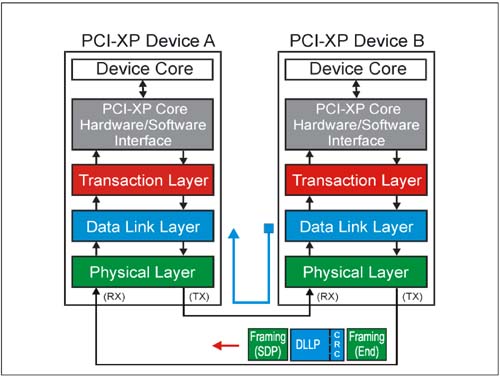
In performing its role, the Data Link Layer exchanges traffic with its neighbor using Data Link Layer Packets (DLLPs). DLLPs originate and terminate at the Data Link Layer of each device, without involvement of the Transaction Layer. DLLPs and TLPs are interleaved on the link. Figure 4-12 on page 198 depicts the transmission of a DLLP from one device to another.
Types Of DLLPs
There are three important groups of DLLPs used in managing a link:
TLP Acknowledgement Ack/Nak DLLPs Power Management DLLPs Flow Control Packet DLLPs
In addition, the specification defines a vendor-specific DLLP.
DLLPs Are Local Traffic
DLLPs have a simple packet format. Unlike TLPs, they carry no target information because they are used for nearest-neighbor communications only.
Receiver handling of DLLPs
The following rules apply when a DLLP is sent from transmitter to receiver:
As DLLPs arrive at the receiver, they are immediately processed. They cannot be flow controlled. All received DLLPs are checked for errors. This includes a control symbol check at the Physical Layer after deserialization, followed by a CRC check at the receiver Data Link Layer. A 16 bit CRC is calculated and sent with the packet by the transmitter; the receiver calculates its own DLLP checksum and compares it to the received value. Any DLLPs that fail the CRC check are discarded. There are several reportable errors associated with DLLPs. Unlike TLPs, the is no acknowledgement protocol for DLLPs. The PCI Express specification has time-out mechanisms which are intended to allow recovery from lost or discarded DLLPs. Assuming no errors occur, the DLLP type is determined and it is passed to the appropriate internal logic: - Power Management DLLPs are passed to the device power management logic - Flow Control DLLPs are passed to the Transaction Layer so credits may be updated. - Ack/Nak DLLPs are routed to the Data Link Layer transmit interface so TLPs in the retry buffer may be discarded or resent.
Sending A Data Link Layer Packet
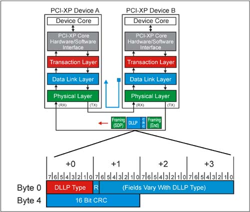
DLLPs are assembled on the transmit side and disassembled on the receiver side of a link. These packets originate at the Data Link Layer and are passed to the Physical Layer. There, framing symbols are added before the packet is sent. Figure 4-13 on page 200 depicts a generic DLLP in transit from Device B to Device A.
Fixed DLLP Packet Size: 8 Bytes
All Data Link Layer Packets consist of the following components:
A 1 DW core (4 bytes) consisting of the one byte Type field and three additional bytes of attributes. The attributes vary with the DLLP type. A 16 bit CRC value which is calculated based on the DW core contents, then appended to it. These 6 bytes are then passed to the Physical Layer where a Start Of DLLP (SDP) control symbol and an End Of Packet (END) control symbol are added to it. Before transmission, the Physical Layer encodes the 8 bytes of information into eight 10-bit symbols for transmission to the receiver.
Note that there is never a data payload with a DLLP; all information of interest is carried in the Type and Attribute fields.
DLLP Packet Types
The three groups of DLLPs are defined with a number of variants. Table 4-17 summarizes each variant as well as their DLLP Type field coding.
Table 4-17. DLLP Packet Types|
Ack
(TLP Acknowledge) | 0000 0000b | TLP transmission integrity | Nak
(TLP No Acknowledge) | 0001 0000b | TLP transmission integrity | PM_Enter_L1 | 0010 0000b | Power Management | PM_Enter_L23 | 0010 0001b | Power Management | PM_Active_State_Request_L1 | 0010 0011b | Power Management | PM_Request_Ack | 0010 0100b | Power Management | Vendor Specific | 0011 0000b | Vendor | InitFC1-P | xxx=VC # | 0100 0xxxb | TLP Flow Control | InitFC1-NP | xxx=VC # | 0101 0xxxb | TLP Flow Control | InitFC1-Cpl | xxx=VC # | 0110 0xxxb | TLP Flow Control | InitFC2-P | xxx=VC # | 1100 0xxxb | TLP Flow Control | InitFC2-NP | xxx=VC # | 1101 0xxxb | TLP Flow Control | InitFC2-Cpl | xxx=VC # | 1110 0xxxb | TLP Flow Control | UpdateFC-P | xxx=VC # | 1000 0xxxb | TLP Flow Control | UpdateFC-NP | xxx=VC # | 1001 0xxxb | TLP Flow Control | UpdateFC-Cpl | xxx=VC # | 1010 0xxxb | TLP Flow Control | Reserved | Others | Reserved |
Ack Or Nak DLLP Packet Format
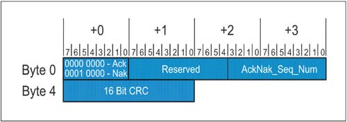
The format of the DLLP used by a receiver to Ack or Nak the delivery of a TLP is illustrated in Figure 4-14.
Definitions Of Ack Or Nak DLLP Fields
Table 4-18 describes the fields contained in an Ack or Nak DLLP.
Table 4-18. Ack or Nak DLLP Fields|
AckNak_Seq_Num [11:0] | Byte 3 Bit 7:0
Byte 2 Bit 3:0 | For an ACK DLLP:
For good TLPs received with Sequence Number = NEXT_RCV_SEQ count (count before incrementing), use NEXT_RCV_SEQ count - 1 (count after incrementing minus 1). For TLP received with Sequence Number earlier than NEXT_RCV_SEQ count (duplicate TLP), use NEXT_RCV_SEQ count - 1.
For a NAK DLLP:
Associated with a TLP that failed the CRC check, use NEXT_RCV_SEQ count - 1. For a TLP received with Sequence Number later than NEXT_RCV_SEQ count, use NEXT_RCV_SEQ count - 1.
Upon receipt, the transmitter will purge TLPs with equal to and earlier Sequence Numbers and replay the remainder TLPs. | Type 7:0 | Byte 0 Bit 7:0 | Indicates the type of DLLP. For the Ack/Nak DLLPs:
0000 0000b = ACK DLLP. 0001 0000b = NAK DLLP.
| 16-bit CRC | Byte 5 Bit 7:0
Byte 4 Bit 7:0 | 16-bit CRC used to protect the contents of this DLLP. Calculation is made on Bytes 0-3 of the ACK/NAK. |
Power Management DLLP Packet Format
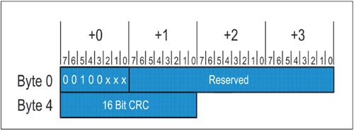
PCI Express power management DLLPs and TLPs replace most signals associated with power management state changes. The format of the DLLP used for power management is illustrated in Figure 4-15.
Definitions Of Power Management DLLP Fields
Table 4-19 describes the fields contained in a Power Management DLLP.
Table 4-19. Power Management DLLP Fields|
Type 7:0 | Byte 0 Bit 7:0 | This field indicates type of DLLP. For the Power Management DLLPs:
0010 0000b = PM_Enter_L1
0010 0001b = PM_Enter_L2
0010 0011b = PM_Active_State_Request
0010 0100b = PM_Request_Ack | Link CRC | Byte 5 Bit 7:0
Byte 4 Bit 7:0 | 16 Bit CRC sent to protect the contents of this DLLP. Calculation is made on Bytes 0-3, regardless of whether fields are used. |
Flow Control Packet Format
PCI Express eliminates many of the inefficiencies of earlier bus protocols through the use of a credit-based flow control scheme. This topic is covered in detail in Chapter 7, entitled "Flow Control," on page 285. Three slightly different DLLPs are used to initialize the credits and to update them as receiver buffer space becomes available. The two flow control initialization packets are referred to as InitFC1 and InitFC2. The Update DLLP is referred to as UpdateFC.
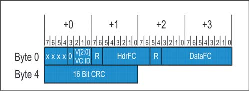
The generic DLLP format for all three flow control DLLP variants is illustrated in Figure 4-16 on page 205.
Definitions Of Flow Control DLLP Fields
Table 4-20 on page 206 describes the fields contained in a flow control DLLP.
Table 4-20. Flow Control DLLP Fields|
DataFC 11:0 | Byte 3 Bit 7:0
Byte 2 Bit 3:0 | This field contains the credits associated with data storage. Data credits are in units of 16 bytes per credit, and are applied to the flow control counter for the virtual channel indicated in V[2:0], and for the traffic type indicated by the code in Byte 0, Bits 7:4. | HdrFC 11:0 | Byte 2 Bit 7:6
Byte 1 Bit 5:0 | This field contains the credits associated with header storage. Data credits are in units of 1 header (including digest) per credit, and are applied to the flow control counter for the virtual channel indicated in V[2:0], and for the traffic type indicated by the code in Byte 0, Bits 7:4. | VC [2:0] | Byte 0 Bit 2:0 | This field indicates the virtual channel (VC 0-7) receiving the credits. | Type 3:0 | Byte 0 Bit 7:4 | This field contains a code indicating the type of FC DLLP:
0100b = InitFC1-P (Posted Requests)
0101b = InitFC1-NP (Non-Posted Requests)
0110b = InitFC1-Cpl (Completions)
0101b = InitFC2-P (Posted Requests)
1101b = InitFC2-NP (Non-Posted Requests)
1110b = InitFC2-Cpl (Completions)
1000b = UpdateFC-P (Posted Requests)
1001b = UpdateFC-NP (Non-Posted Requests)
1010b = UpdateFC-Cpl (Completions) | Link CRC | Byte 5 Bit 7:0
Byte 4 Bit 7:0 | 16 Bit CRC sent to protect the contents of this DLLP. Calculation is made on Bytes 0-3, regardless of whether fields are used. |
Vendor Specific DLLP Format
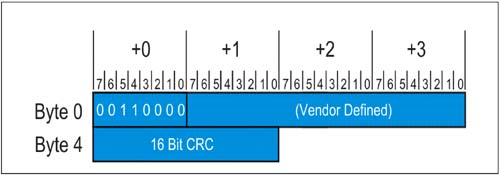
PCI Express reserves a DLLP type for vendor specific use. Only the Type code is defined. The Vendor DLLP is illustrated in Figure 4-17.
Definitions Of Vendor Specific DLLP Fields
Table 4-21 on page 207 describes the fields contained in a Vendor-Specific DLLP
Table 4-21. Vendor-Specific DLLP Fields|
Type 3:0 | Byte 0 Bit 7:4 | This field contains a code indicating the Vendor-specific DLLP:
0011 0000b = Vendor specific DLLP | Link CRC | Byte 5 Bit 7:0
Byte 4 Bit 7:0 | 16 Bit CRC sent to protect the contents of this DLLP. Calculation is made on Bytes 0-3, regardless of whether fields are used. |
 | 
