| [ Team LiB ] |


|
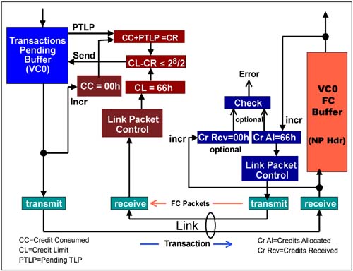
Operation of the Flow Control Model - An ExampleThe purpose of this example is to explain the operation of the Flow Control mechanism based on the conceptual model presented by the specification. The example uses the non-posted header Flow Control buffer type, and spans four stages to capture the nuances of the flow control implementation: Stage One — Immediately following initialization, the several transactions are tracked to explain the basic operation of the counters and registers as they track transactions as they are sent across the link. In this stage, data is accumulating within the Flow Control buffer, but no transactions are being removed. Stage Two — If the transmitter sends non-posted transactions at a rate such that the Flow Control buffer is filled faster than the receiver can forward transactions from the buffer, the buffer will fill. Stage two describes this circumstance. Stage Three — The modulo counters are designed to roll over and continue counting from zero. This stage describes the flow control operation at the point of the CREDITS_ALLOCATED count rolling over to zero. Stage Four — The specification describes the optional error check that can be made by the receiver in the event of a Flow Control buffer overflow. This error check is described in this section. Stage 1 — Flow Control Following InitializationThe assumption made in this example is that flow control initialization has just completed and the devices are ready for normal operation. The Flow Control buffer is presumed to be 2KB in size, which represents 102d (66h) Flow Control units with 20 bytes/header. Figure 7-5 on page 295 illustrates the elements involved with the values that would be in each counter and register following flow control initialization. Figure 7-5. Flow Control Elements Following Initialization
The transmitter must check Flow Control credit prior to sending a transaction. In the case of headers the number of Flow Control units required is always one. The transmitter takes the following steps to determine if the transaction can be sent. For simplicity, this example ignores the possibility of data being included in the transaction. The credit check is made using unsigned arithmetic (2's complement) in order to satisfy the following formula:
Substituting values from Figure 7-5 yields:
Figure 7-6 on page 297 illustrates the Flow Control elements following transfer of the first transaction. Figure 7-6. Flow Control Elements Following Delivery of First Transaction
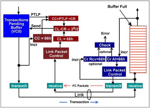
Stage 2 — Flow Control Buffer Fills UpThis example presumes that the receiving device has been unable to move transactions from the Flow Control buffer since initialization. This could be caused if the device core was temporarily busy and unable to process transactions. Consequently, the Flow Control buffer has completely filled. Figure 7-7 on page 299 illustrates this scenario. Figure 7-7. Flow Control Elements with Flow Control Buffer Filled
Again the transmitter checks Flow Control credits to determine if the next pending TLP can be sent. The unsigned arithmetic is performed to subtract the Credits Required from the CREDIT_LIMIT:
Not until the receiver moves one or more transactions from the Flow Control buffer can the pending transaction be sent. When the first transaction is moved from the Flow Control buffer, the CREDIT_ALLOCATED count is increased to 67h. When the Update Flow Control packet is delivered to the transmitter, the new CREDIT_LIMIT will be loaded into the CL register. The resulting check will pass the test, thereby permitting the packet to be sent.
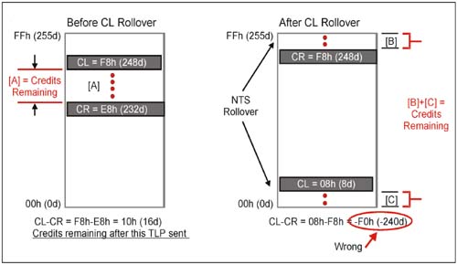
Stage 3 — The Credit Limit count Rolls OverThe receiver's CREDIT_LIMIT (CL) always runs ahead of (or is equal to) the CREDITS_CONSUMED (CC) count. Each time the transmitter performs a credit check, it adds the credits required (CR) for a TLP to the current CREDITS_CONSUMED count and subtracts the result from the current CREDIT_LIMIT to determine if enough credits are available to send the TLP. Because both the CL count and the CC count only index up, they are allowed to roll over from maximum count back to 0. A problem appears to arise when the CL count (which, again, is running ahead) has rolled over and the CC has not. Figure 7-8 shows the CL and CR counts before and after CL rollover. Figure 7-8. Flow Control Rollover Problem
If a simple subtraction is performed in the rollover case, the result is negative. This indicates that credits are not available. However, because unsigned arithmetic is used the problem does not arise. See below:
Stage 4 — FC Buffer Overflow Error CheckThe specification recommends implementation of the optional FC buffer overflow error checking mechanism. These optional elements include:
These elements permit the receiver to track Flow Control credits in the same manner as the transmitter. That is, the transmitter CREDIT_LIMIT count should be the same as the receiver's CREDITS_ALLOCATED count (after an Update DLLP is sent) and the receiver's CREDITS_RECEIVED count should be the same as the transmitter's CREDITS_CONSUMED count. If flow control is working correctly the following will be true:
An overflow condition is detected when the following formula is satisfied. Note that the field size is either 8 (headers) or 12 (data):
If the formula is true, then the result is negative; thus, more credits have been sent to the FC buffer than were available and an overflow has occurred. Note that the 1.0a version of the specification defines the equation as |
 2[
2[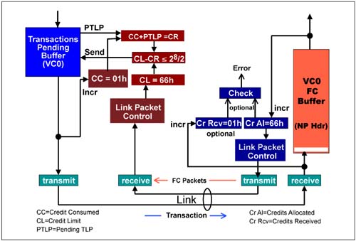
 rather than > as shown above. This appears to be an error, because when CA=CR no overflow condition exists. For example, for the case right after initialization where the receiver advertises that it has 128 credits for the transmitter to use, CA = 128, and CR = 0 because it hasn't received anything yet, then this equation evaluates true. Which means it has overflowed, when actually all we have done is advertise our max allowed number of credits. If the equation evaluates for only > and not
 | [ Team LiB ] |
|