The Hot-Plug Controller Programming Interface
The standard programming interface to the Hot-Plug Controller is provided via the PCI Express Capability register block. Figure 17-4 on page 670 illustrates these registers and highlights the registers that are implemented by the different types of devices. Hot Plug features are primarily provided via Slot Registers that are defined for root and switch ports. The Device Capability register is also used in some implementations as described later in this chapter.
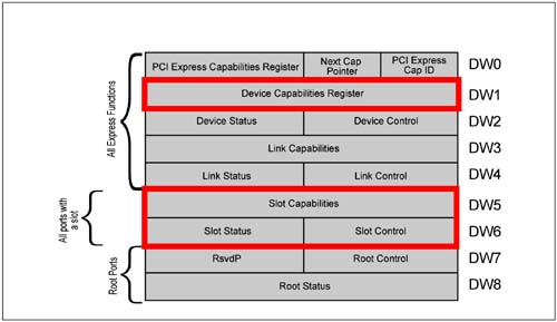
Slot Capabilities
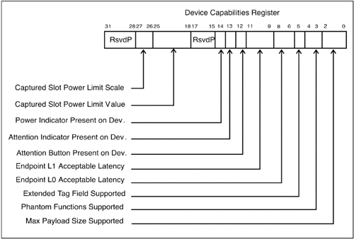
Figure 17-5 on page 671 illustrates the slot capability register and bit fields. Hardware must initialize the capability register fields to reflect the features implemented by this port. This register applies to both card slots and rack mount implementations, except for the indicators and attention button. Software must read from the device capability register within the module to determine if indicators and attention buttons are implemented. Table 17-5 on page 671 lists and defines the slot capability fields.

Table 17-5. Slot Capability Register Fields and Descriptions|
0 | Attention Button Present —
when set, indicates that an attention button is located on the chassis adjacent to the slot. | 1 | Power Controller Present —
when set, indicates that a power controller is implemented for this slot. | 2 | MRL Sensor Present —
when set, indicates that a MRL Sensor is located on the slot. | 3 | Attention Indicator Present —
when set, indicates that an attention indicator is located on the chassis adjacent to the slot. | 4 | Power Indicator Present —
when set, indicates that a power indicator is located on the chassis adjacent to the slot. | 5 | Hot-Plug Surprise —
when set, indicates that it is possible that the user can remove the card from the system without notification. | 6 | Hot-Plug Capable —
when set, indicates that this slot supports hot plug operation. | 14:7 | Slot Power Limit Value —
specifies the maximum power that can be supplied by this slot. This limit value is multiplied by the scale specified in the next field. | 16:15 | Slot Power Limit Scale —
specifies the scaling factor for the Slot Power Limit Value. | 31:19 | Physical Slot Number —
Indicates the physical slot number associated with this port. |
Slot Power Limit Control
The specification provides a method for software to limit the amount of power consumed by a card installed into an expansion slot or backplane implementation. The registers needed to support this feature are included in the hot plug capable port within the Slot Capability register and within the expansion card or module within the device capability register.
Slot Control
Software controls the Hot Plug events via the Slot Control register. This register permits software to enable various Hot Plug features and to control hot plug operations. Figure 17-6 on page 673 depicts the slot control register and bit fields. Table 17-6 on page 673 lists and describes each field. This register acts as the programming interface to control various Hot-Plug features and to enable interrupt generation as well as enabling the sources of Hot-Plug events that can result in interrupt generation.
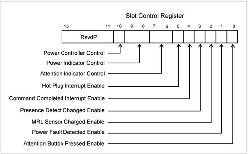
Table 17-6. Slot Control Register Fields and Descriptions|
0 | Attention Button Pressed Enable.
When set, this bit enables the generation of a hot-plug interrupt (if enabled) or assertion of the Wake# message, when the attention button is pressed. | 1 | Power Fault Detected Enable.
When set, enables generation of a hot-plug interrupt (if enabled) or Wake# message upon detection of a power fault. | 2 | MRL Sensor Changed Enable.
When set, enables generation of a hot-plug interrupt or Wake# (if enabled) message upon detection of a MRL sensor changed event. | 3 | Presence Detect Changed Enable.
When set this bit enables the generation of the hot-plug interrupt or a Wake message when the presence detect changed bit in the Slot Status register is set. | 4 | Command Completed Interrupt Enable.
When set, enables a Hot- Plug interrupt to be generated that informs software that the hot-plug controller is ready to receive the next command. | 5 | Hot-Plug Interrupt Enable.
When set, enables the generation of Hot-Plug interrupts. | 6 | Attention Indicator Control.
Writes to the field control the state of the attention indicator and reads return the current state, as follows:
00b = Reserved 01b = On 10b = Blink 11b = Off
| 7 | Power Indicator Control.
Writes to the field control the state of the power indicator and reads return the current state, as follows:
00b = Reserved 01b = On 10b = Blink 11b = Off
| 8 | Power Controller Control.
Writes to the field switch main power to the slot and reads return the current state, as follows:
0b = Power On 1b = Power Off
|
Slot Status and Events Management
The Hot Plug Controller monitors a variety of events and reports these events to the Hot Plug System Driver. Software can use the "detected" bits to determine which event has occurred, while the status bit identifies that nature of the change. The changed bits must be cleared by software in order to detect a subsequent change. Note that whether these events get reported to the system (via a system interrupt) is determined by the related enable bits in the Slot Control Register.
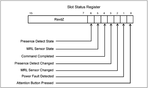
Table 17-7. Slot Status Register Fields and Descriptions|
0 | Attention Button Pressed —
set when the Attention Button is pressed. Notification of the attention button being pushed depends on the form-factor implemented:
standard card slots use a signal trace to report the event rack and backplane implementations may rely on the Attention_Button_Pressed message. refer to other form-factor specs for details regarding those implementations.
| 1 | Power Fault Detected —
set when the Power Controller detects a power fault at this port. | 2 | MRL Sensor Changed —
set when a MRL Sensor state change is detected. | 3 | Presence Detect Changed —
set when a change has been detected in the state of the Prsnt1# or Prsnt2# signals. | 4 | Command Completed —
set when the Hot Plug Controller completes a software command. | 5 | MRL Sensor State —
when set, indicates the current state of the MRL sensor, if implemented.
0b = MRL Closed
1b = MRL Open | 6 | Presence Detect State —
this bit reflects whether a card is installed into a slot or not (set if card present, clear if card not present). It is required for all root and switch ports that have a slot attached to the link. The specification also states that if a slot is not attached to the link, then this bit "should be hardwired to 1." |
Card Slot vs Server IO Module Implementations
PCI Express supports two form factors that determine the location of the Hot-Plug indicators and attention button (See Figure 17-8 on page 677):
Standard Cards that reside in PCI-like slots —
motherboard or expansion chassis implementations place Hot Plug indicators, the attention button, and MRL sensor adjacent to each slot on the board.
Server IO Modules (SIOMs) that install into racks —
when modules are installed into a rack-mounted system the hot-plug indicators and attention button may be located more conveniently on the PCI Express modules as opposed to a Rack. However the specification does not preclude the possibility of indicators and buttons being located on module bays.
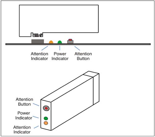
In addition to Server IO Modules, cards (or blades) that install into backplanes may also have indicators and the attention button located on the card. These implementations were not defined at the time of this writing. However, proposted SIOM implementations route the attention button and attention indicator signals through the connector.
The specification also defines messages that act as virtual wires for controlling the attention indicators and for reporting when the attention button has been pressed. The approach eliminates the need to route signals between the port and connector for the attention indicators and attention button, as done with card slots as illustrated in Figure 17-3 on page 669. See "Hot Plug Messages" on page 678.
Detecting Module and Blade Capabilities
Hot-Plug ports that attach to rack and backplane connectors may not know whether a given module or blade includes indicators or an attention button. Consequently, the specification includes this information within the Device Capabilities register. See Figure 17-9 on page 678.
Hot Plug Messages
When the Hot-Plug indicators and attention button are located on a module or blade, messages can be used as virtual wires to control the indicators and to report that the button has been pressed.
Attention and Power Indicator Control Messages
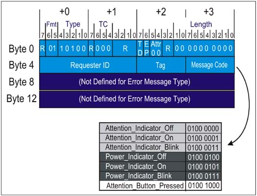
As discussed in Table 17-6 on page 673, the attention and power indicators each have three states: on, off, and blinking. The message transactions act as virtual wires to signal the attention indicator state. Figure 17-10 on page 680 illustrates the Hot Plug Message format and lists the values associated with each of the messages.
Attention_Indicator_On.
This message is issued by the Hot Plug Controller when software writes a value of 01b into the Attention Indicator Control field of the Slot Control Register indicating that the Attention Indicator is to be turned on. The endpoint device that receives the message terminates it and causes the card's attention indicator to turn on.
Attention_Indicator_Blink.
This message is issued by the Hot Plug Controller when software writes a value of 10b into the Attention Indicator Control field of the Slot Control Register indicating that the Attention Indicator is to blink on and off. The endpoint device that receives the message terminates it and causes the card's attention indicator to start blinking.
Attention_Indicator_Off.
This message is issued by the Hot Plug Controller when software writes a value of 11b into the Attention Indicator Control field of the Slot Control Register indicating that the Attention Indicator is to be turned off. The endpoint device that receives the message terminates it and causes the card's indicator to turn off.
Power_Indicator_On.
This message is issued by the Hot Plug Controller when software writes a value of 01b into the Power Indicator Control field of the Slot Control Register indicating that the Power Indicator is to be turned on. The endpoint device that receives the message terminates it and causes the card's power indicator to turn on.
Power_Indicator_Blink.
This message is issued by the Hot Plug Controller when software writes a value of 10b into the Power Indicator Control field of the Slot Control Register indicating that the Power Indicator is to blink on and off. The endpoint device that receives the message terminates it and causes the power indicator to blink.
Power_Indicator_Off.
This message is issued by the Hot Plug Controller when software writes a value of 11b into the Power Indicator Control field of the Slot Control Register indicating that the Power Indicator is to be turned off. The endpoint device that receives the message terminates it and causes the card's power indicator to turn off.
Attention Button Pressed Message
A module or blade that employs an attention button must signal the Hot Plug Controller that the button has been pressed. The module generates an Attention_Button_Pressed message (Figure 17-10 on page 680) that targets the upstream device (root or switch port). The message results in an Attention Button Pressed Event that causes the Attention Button Pressed status bit in the Slot Status register bit to be set, and may also result in an interrupt if enabled.
Limitations of the Hot Plug Messages
Note that these features function only when the card is installed and operational. Thus, indicators can be controlled prior to card removal and similarly the card can report that the attention button has been pressed (e.g., to signal a request for card removal). However, when a new card is installed, the attention button message cannot be sent from the card and attention indicator messages cannot be received until the card is re-powered, reconfigured, and enabled. This means that software will have to be notified that a card is ready to be re-installed.
|

