Check out my first novel, midnight's simulacra!
A case study in full-stack device development: the dankdryer
dankblog! 2024-09-29, 2329 EDT, at the danktower
update: this has been improved, and improved a bit more than that, and is now available for purchase!
Materials like PA (nylon), PVA, and TPU tend to be fairly hygroscopic, meaning that they collect and retain moisture. It is said that PVA filament can retain more than 10% of its weight in water. Wet filament can ruin a print two ways: hydrolysis reactions break up polymers, rendering filament brittle and negatively affecting its mechanical properties, and moisture can flash into steam in the hotend. Water is many times less dense in its gaseous form, and in the small volume of a hotend, it'll exert tremendous pressure, affecting material flow. Moisture furthermore promotes generation of particulate matter during printing, undesirable for breathing even when it's not explicitly carcinogenic or otherwise toxic.
PLA, PETG, ABS, and ASA will not generally absorb more than ~2% of their weight, but this still results in stringing, zits, and weaker output. Expensive engineering filaments can be rendered completely unusable through exposure to even light humidity. If you're in a humid region, drying your filament is a must. Unfortunately, most filament dryers on the market can't get above 70℃, have a difficult time maintaining even that temperature, and are generally terribly designed. Engineering filaments are best dried using temperatures over 100℃: Bambu recommends 140℃ for their PPS-CF and PPA-CF filaments. You won't touch this temperature outside of an oven. Blast ovens work well, but are prohibitively expensive. Kitchen convection ovens set to such (relatively) low temperatures tend to control them poorly (just search for "melted spools"). Even if you don't melt your filament down, you're filling your cooking area with potentially toxic material. Either way, ovens tend to be inefficient, radiating much of their heat away without applying it to the filament.
Beyond drying, it is sometimes desirable to anneal a print following completion. Annealing temperatures tend to run with drying temperature (technically, you want the material's glass transition temperature), and thus a higher-power device can be useful after the print as well.
I set out to build a better filament dryer. I wasn't designing for mass manufacture, but I did concern myself with printability, ease of assembly, and repairability. I wanted it capable of 150℃, safe with regards to both heat and electricity, and efficient. And dank. This project is and always will be Open Source. Models and firmware are available on GitHub. I've provided links to datasheets for each IC; read these datasheets if you intend to build something similar.
Requirements
- The device must provide even heating up to 150℃ to the spool, at a constant temperature.
- The device must not deform or fail under such temperatures.
- Moisture ought be removed from the device.
- The device must acquire and maintain connection to a preconfigured WiFi network, get a DHCP lease, and announce mDNS.
- The device must be controlled, and report status/measurements, using HTTP and/or MQTT.
- The device must be powered by AC mains.
- The device must measure internal humidity and temperature.
- The device ought measure weight of the spool, ideally with accuracy within 1% (10g at 1kg).
- The device ought support OTA, with custom data persisted across the update.
Stretch goals
- The device ought read spool RFID tags, and when possible schedule optimal drying parameters.
- The device ought, upon recovery from power loss, continue the drying operation.
Macrodesign
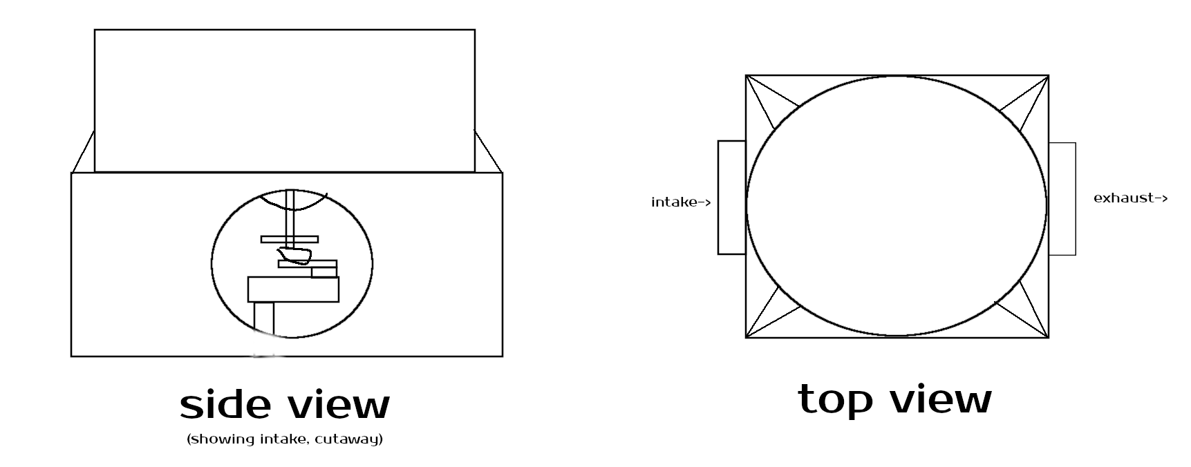
The dryer will be printed, rather than cast from metal or injection moulded, because I have access to a good 3D printer. Most electronics have difficulties working over 60℃, let alone at 150℃, so I need to keep them thermally isolated from the heating area. This suggests a two-chamber design. Unless one uses a circular heating element, the spool must be rotated for even heating. Filament dryers usually stand the spool up, but I want to lay it down, figuring it would be easier to rotate this way (plus harder to knock over) at the cost of occupying greater area. Having decided this, a hot box atop a cool chamber is an obvious choice. I want fans, both to actively cool the electronics, and to remove moisture cooked out of the filament. Intake of the exhaust is undesirable, so fans need to be on different sides of the device, and I'll need air to flow up and into the hotbox from the coolbox. Given the need for thermal isolation, there will be a divider between the two chambers. This pretty much mandates printing them as distinct pieces (the dividing floor will otherwise need be printed with supports).
Weighing the spool means it must be supported by the load cell. Accurate measurements require minimizing the load on the cell due to other structures, isolating the load cell from heat and airflow (and correcting for them otherwise), and keeping the spool centered. The load cell will thus need be kept in the center of the bottom chamber, ideally high up to minimize load due to spool support. The load cell can't rotate, since it has wires connecting it to the amplifier (and subsequently the MCU). The heavy motor can't be supported by the load cell. A gear will thus be necessary to transfer torque from a motor to the spool platform. So atop the load cell will be a coupling holding a bearing, a gear, and a platform for the spool. These components can all be printed distinctly, and joined together, eliminating the need for supports. The bearing will then sit in the coupling (likewise printed on its own), which will be screwed into the load cell.
1kg spools tend to be about 70mm thick. This suggests use of 80mm fans, especially since I have several Noctua NF-A8s on hand. Each chamber will thus be about 90mm tall. Diameter of the hotbox will need be about 21cm to accommodate typical spools, and it will be a cylinder so that the spool doesn't have room to move. I need to fit an AC adapter, a perfboard/PCB, the central column, and a motor into the coolbox; ideally this won't require more area than the hotbox (I want the AC adapter inside since I'll need run AC to the heating element directly, and don't want to split the dangerous 120V AC outside the device). If the motor is mounted perpendicular to the column, a worm gear will facilitate orthogonal transfer of torque to the central shaft. If the motor is standing vertically, I'd probably want to use a belt.
Basically, I want something like this (not drawn to scale):
Parts
I wanted to use stuff I already had if it was at all suitable. As a result, my BOM was higher than it ought be, and some parts are probably not the best ones I could have possibly used.
Filaments
Of what I had available, polycarbonate and PAHT-CF were the most heat resistant. Both Bambu polycarbonate and Polymaker PolyLite PC claim Vicat softening points of 119℃ and melting points well above 200℃ (228 and 260, respectively). Bambu's PAHT-CF (carbon fibre-reinforced Nylon 12) melts at 225, but doesn't soften until 220. I had a half kilogram of this, plus another half kilogram of Atomic Filament Nuclear Nylon (cabon fibre-reinforced Nylon 6). I thus used nylon for both chambers, especially as it holds its shape very precisely, allowing close mating of the chambers. I did the other parts with PolyLite PC.
Rotational/mechanical
| Screws | Purpose |
|---|---|
| 4x M5x45 | Hotbox→cool chamber |
| 2x M3x6 | Buck converter→mount |
| 2x M3x8 | AC adapter→mount |
| 2x M3x6 | RC522→hotbox exterior |
| 2x M3x6 | Thermostat switch→hotbox exterior |
| 2x M3x6 | Heating element→hotbox interior |
| 2x M3x8 | Perfboard→mount |
| 8x M4x8 | 2x fans (4 each)→exterior |
| 2x M4x12 | Coupling→brace→load cell |
| 2x M4x20 | Load cell→mount |
| 6x M3x8 | Motor→mount |
As noted earlier, I'd be using two Noctua NF-A8 chromax.black 80mm fans. They are in a square form factor, but the actual spinning area is circular, π40² ~= 5026.5mm². I had a pack of 608 bearings, which seemed like they'd work fine; 608 it was (narrator: they would not work, and I upgraded to a larger 6200-2RS for stability; this required modifying and reprinting the lower coupling). Finally, I used a Geartisan 12V 5RPM DC motor, by which I was pretty disappointed (it's louder than it seems it ought be, stalls easily despite the very low RPMs, and I can't find an official datasheet).
I've included a model for a 6200-2RS bearing, but recommend you unass $2 for a real one.
Electronics
As noted before, the device is driven off 60Hz 120V AC mains. I need AC for my heating unit, but DC for my electronics, so an AC adapter is required. I had a sleek, sexy 160W 12V adapter on hand, complete with grounding connection and two 12V outputs. One output would go to my motor controller and fans; the other would go to an LM2596 buck converter for stepdown to 5V.
DC
For my MCU, I wanted to use the ESP32-S3, of which I had several in my possession. Like all ESP32s, this is a dualcore XTensa 3.3V SoC with 2.4GHz WiFi and Bluetooth. Were I designing for mass manufacture, I'd certainly want to design a custom PCB, but as a one-off I was satisfied with perfboard and a devkit. I wanted to power the MCU by USB-C, so that I could easily power it from my computer during testing. I would thus need a USB-C connector with pigtails to solder to the LM2596.
Rectangular load cells are much cheaper than circular ones, or a collection of point cells, and ought be serviceable so long as the spool is kept centered. Accuracy is inversely proportional to total weight capacity for a given load cell technology, so I went with a 5kg bar cell and an accompanying NAU7802 24-bit DAC + amplifier (I went for the NAU7802 over the more common HX711 because it offers an I2C interface). The NAU7802 (like the HX711) works better with 5V for analog power, so we'll take a line out to it from the LM2596. An RC522 reads 15.96MHz RFID. The ESP32-S3 has a builtin chip temperature sensor, and my humidity sensor (a BME680) brings another one to the table. Between them, I ought be able to get a reliable temperature for the cool box, necessary for temperature correction of the load cell readings. A TB6612FNG motor controller can supply a sustained 1.2A (peak 3.2A) of 12V, while supporting 3.3V logic. I needed two Molex 4-pin connectors for the fans, using 12V for power and 3.3V for the tach and PWM signal.
An ESP32 can peak at 40mA sourced from a pin, but ought be kept at 20mA or below. The NAU7802 and TB6612FNG are both submilliamp devices, and can be easily powered from the ESP32's 3.3V bus and a single pin. The BME680 consumes 20mA peak (when it's turning on its hotplate), and cruises at 12mA if doing gas detection, but needs only microamps for humidity/temperature/pressure. It should be fine. The RC522 is another story, capable of pulling 100mA, and drinking down a meaty 60mA in its steady state. It'll need its own 3.3V power supply, using either a second buck converter off the 12V source or a voltage divider from 5V. If we implement the latter using a 1.5kΩ and 2.2kΩ resistor, we drop to 2.973V, wasting 2.027V (a peak dissipation of ~200mW and typical ~125mW as heat).
| Component | Voltage | Max mA | Usual mA |
|---|---|---|---|
| BME680 | 1.71–3.6 | 20 | <1 |
| TB6612FNG | 2.7–5.5 | <1 | <1 |
| NAU7802 | 2.7–5.5 | 2.1 | 2.1 |
| RC522 | 2.5–3.3 | 100 | 40 |
| LM35ZD | 4–30 | <1 | <1 |
| Fan PWM | 2.5–5 | 5 | 5 |
In the hotbox, I wanted nothing other than a heating element and thermostat. The LM35ZD thermostat is rated up to 150℃, unlike the more common DS18B20 (unfortunately, it wants at least 4V, so we can't run it off our ESP32's 3.3V bus. The 5V will be fine, though, and we needn't adjust the output voltage, because the maximum 150C ought be 1.5V). A cheap ceramic rectangular heater generates up to 230℃.
In terms of small components, each fan would require a 1KΩ and 3.3KΩ resistor and a 0.1nF capacitor for its tach circuit. We need a 120Ω resistor for the triac. I'd need 7 ring terminals to interface with the AC adapter (4 on the DC side, 3 on the AC side), and a 2-to-4 XHF connector to split the incoming AC live+neutral lines. A grommet would line the hole through which the AC cable entered the device; I had one on hand, but could otherwise have printed one with TPU. The motor controller's TVS diode ought keep the splashback from our motor's inductive load from blowing up our sensitive ICs; likewise the optocoupler for our AC network. We'll need a 2.2K and 1.5K resistor assuming we don't use a second buck converter.
AC
Whereas the motor simply needs to be turned on at the start of a drying operation, and off at the end (presumably hours later), the heater is another story. I don't want the coarse control (and limited lifetime operations) of a relay; I'd either sacrifice tight control of the temperature, or be switching the relay off and on regularly. At first, I thought I'd control the heater with PWM. Proper multihertz PWM with AC requires a solid state relay plus zero crossing detection. Given the slow transitions between temperatures, however, such fine-grained PWM isn't necessary. An SSR, basically operating as an AC MOSFET, ought suffice, without the limited lifetime of a mechanical relay. The BT136-600E in conjunction with a MOC3061 optocoupler look suitable for my needs, with a 1.4V gate voltage, a 10mA trigger current, a 2.2mA holding current, and the ability to shuffle 4A. A 150℃ NC (normally closed) thermostat switch provides a hardware killswitch in the event of thermal runaway.
Finally, we need a NEMA AC cable and a 5A inline fuse.
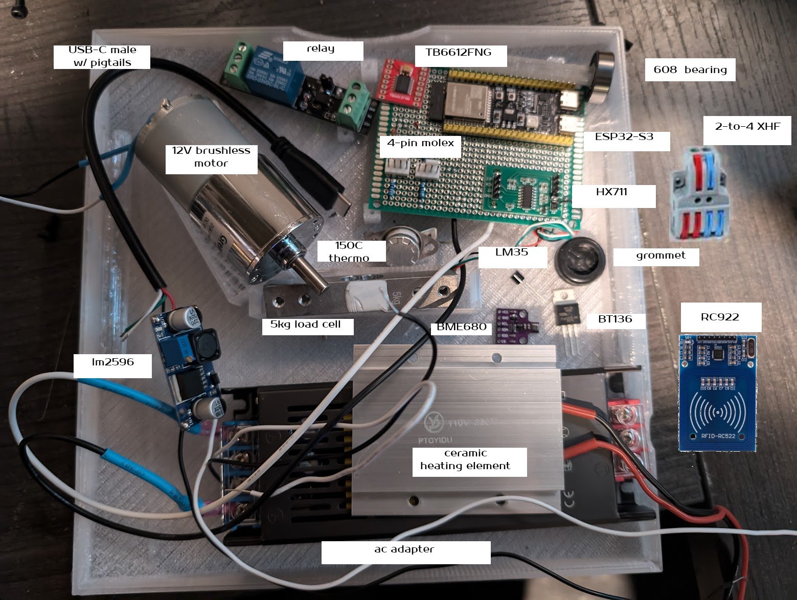
Thus, the components (fans/fuse not shown, resistors/capacitors not labeled, relay was not used):
Models
I designed everything in OpenSCAD. These are somewhat complex models; a recent (2023+) build of OpenSCAD with the Manifold renderer enabled will make your experience much more pleasant. In addition to the printed parts, I modeled the load cell, AC adapter, and motor, so that I could design around them.
Cool chamber
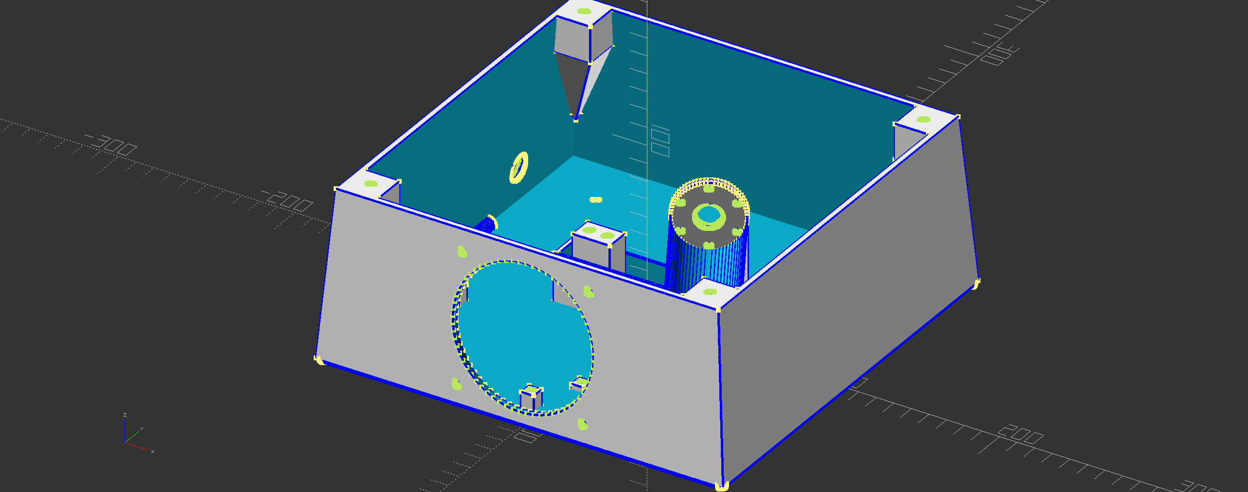
The cool chamber is a hollow truncated pyramid. There is a circular hole for its fan, and a much smaller circular hole for the AC cable. The top is open save for the four corners, which expose M5 mounts by which the hotbox is joined to the cool chamber. These each recede into the corner, eliminating the need for supports. The AC adapter, perfboard, and LM2596 are mounted to the floor, with four short mounts each. These allow wires to be run underneath the components, and help smooth out any unevenness due to floor warping. The motor is placed atop a tall mount, and affixed with six M2 screws to a cojoined front plate. The load cell is joined to a smaller mount; this mount does not run its full length, as the load cell needs be able to dip on one side. Two channels run along the sides to guide wires running to the AC adapter. The intake fan is mounted on the outside. The floor is beveled to help fight warping. Incoming cool air runs directly over the perfboard and buck converter, around the load cell's air shield, over the AC adapter, and up into the hotbox.
A small inlet is cut into the top opposite the intake fan for the exhaust fan's wires.
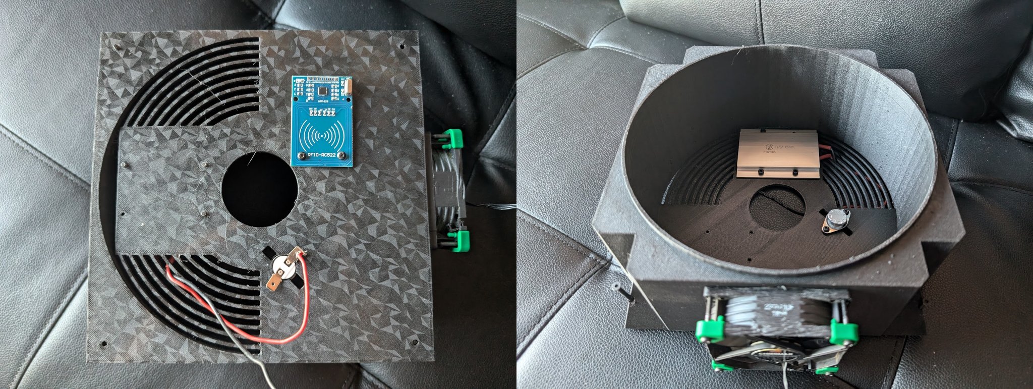
Note that the optocoupler+triac and RFID reader have no mounts; they are instead mounted to the underside of the hotbox. Hopefully this won't be too hot for their reliable function: we'll have to test and see. The RFID reader ought work across 50mm.
Hotbox
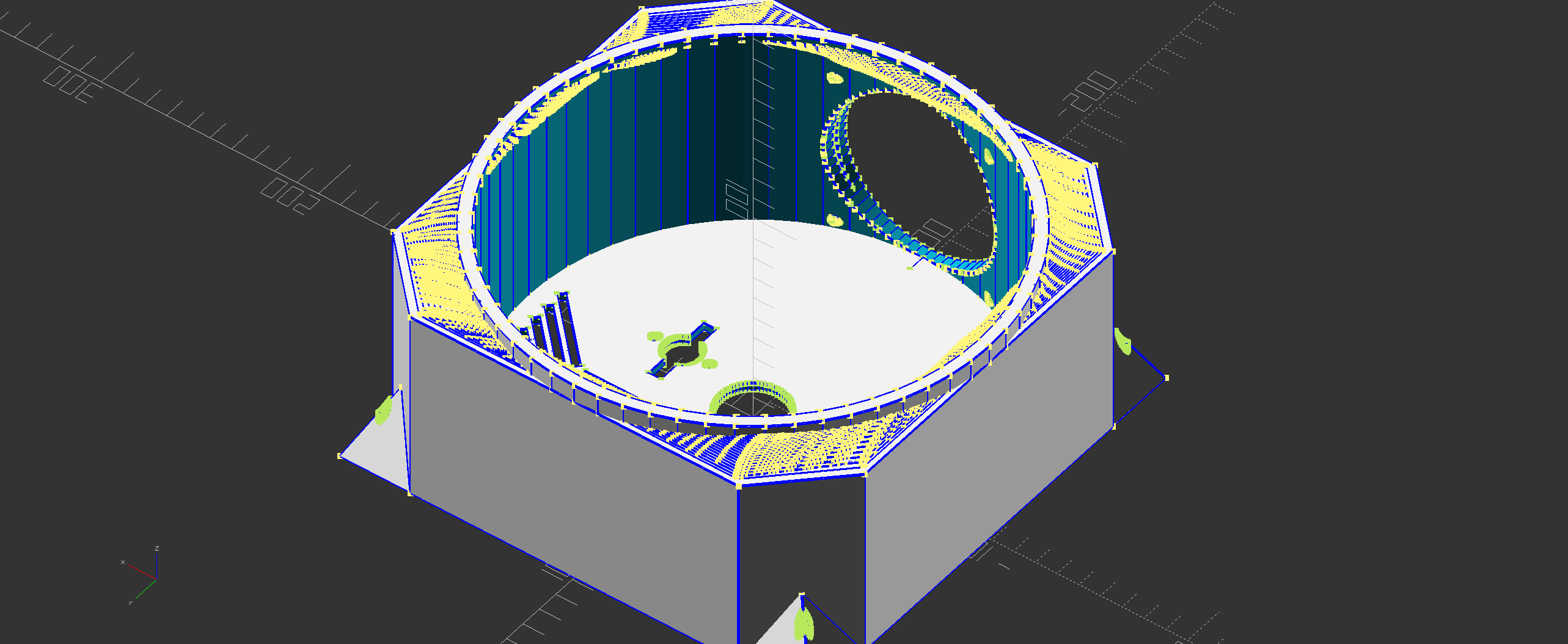
The hotbox is fundamentally a cylinder circumscribed by an octagonal prism with four half-pyramid mounts by which it is joined to the cool chamber. A hole is cut away from the floor in which the thermocouple sits, exposing its terminals into the cool chamber. More importantly, this allows us to solder the AC circuit externally to the hotbox—we don't want wires running along the hotbox floor! Mounting points similarly exist for the relay and RFID reader, which will be mounted upside-down to the underside. The heater will actually be mounted in the hot chamber, and the spool platform will thus have to rise half a centimeter or so above the floor so the spool is not obstructed.
Remember from earlier that an 80mm circular fan has just over 5026mm² of area through which to push or pull air. We want an equal amount of ventilation between the two chambers, so all this air can flow naturally. The ventilation is provided as a series of concentric arcs on the heater's side of the hotbox, symmetric across the y axis. Air will thus hopefully flow in, circulate in the cool chamber, go up into the heating area, and finally distribute the heat and remove any moisture. I thought about trying to collect this moisture, condense it, and just weigh that (as opposed to the spool), but such an approach seemed in the end far more complex and less reliable than a spool measurement. I need to smoketest the airflow, but at worst, it seems that the AC adapter might not get any cooling. I doubt it really needs any. The grommet ought prevent much air from escaping out the AC wire hole.
Placement of the heating element posed an interesting problem. Spool rotation solves the problem of even heating along the circumference, but what about the radius? Placing the heater in the center is in any case a non-starter due to the structure of the central column, but it would furthermore result in very uneven heating, with most of the heat being applied to the inner loops of filament. Instead, let's solve for the center of mass of an annular sector of the spool; ignoring air effects and the possibility of partially-consumed spools, this ought be the optimal place to center the heater. Using a quick bit of calculus, we establish the centroid of an annular sector of a disk having internal radius r₁ and external radius r₂ subtending θ to be (4sin(θ/2)(r₂³-r₁³))/(3θ(r₂²-r₁²)) along the radius. Whether this calculation has any real-world merit or is simply false assurance dressed up in math is left as an exercise for the reader.
It doesn't seem possible to evenly heat the spool across its width (height in our orientation) unless the heater was stood up along the outside, which would make heating very uneven across the (larger and thus more significant) radius. We can get symmetric heating along this axis three ways: continuous rotation along this axis (necessitating a spherical hotbox), regular flipping of the spool (a special case of rotation, and difficult to do automatically), or placing heaters both on the floor and roof of the hotbox. If this ends up being a big problem, I'll add a ceiling heater. I consider this the main theoretical shortcoming of the dryer, though I'm not yet sure whether it'll matter in practice.
We cut the corners out of the top, both to save on material, and because it looks kinda cool imho.
Small parts/top/platform
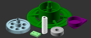
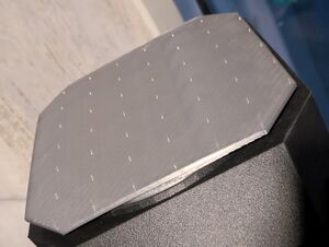
We still need the central column and the gears. I divided the pieces up so they would print more easily; this is no cost, since we're using screws to join them to the load cell already.
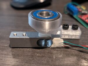
The worm gear goes on the rotor of the motor. It must be tangent to some point on the main gear. The platform, gear, and finally bearing are all connected, and the bearing then rests in the coupling, where it can freely rotate. The coupling is screwed using 2 M4x12s into the brace, which is screwed into the top of the load cell (the brace lifts the coupling above the cell's glue). It's easiest to push the platform through the central shaft of the hotbox, mount the gear onto it, and mount the bearing onto the gear.
We could print the platform and main gear as a single piece without supports, but our gear could then only be as wide as the central hole in the hotbox. By decoupling them, and inserting only the platform shaft through the hole, the gear can be as large as we want. This gives us a lot more flexibility in placement of the motor mount (a larger gear allows us to place the motor mount further away from the center), which we need in order to accommodate the large load cell.
The top is a simple cylinder with a backing plate which fits snugly into the hotbox. I should probably add some kind of latching mechanism. What would be truly ideal is feedback to the MCU regarding whether the top is present, so it could make decisions based on its state. It was printed using Bambu Clear Black polycarbonate on smooth PEI. Quoth the raven, "what a shine!"
Assembly
Alright, let's print this sumbitch! I printed the cool chamber on textured PEI, and everything else on smooth PEI. Everything was printed on my Bambu X1C using the 0.20mm Standard preset with infill combination, 8% sparse infill density, cross hatch sparse infill pattern, and the Arachne wall generator, except the gears and platform, which were printed using 0.16mm High-Quality plus 50% sparse infill with gyroid.
Hotbox
I printed the previous iteration of the hotbox using Bambu PAHT-CF, but ran out of it, and thus this final version is AF Nuclear Nylon on smooth PEI. Mount the RC522 to its four mounting stands, and through them to the underside of the hotbox. Install the ceramic heating element and the thermocouple, leaving wires and terminals hanging out of the bottom. Install the fan on the outside, facing out. We thread four M5x45 bolts through the corners in preparation for mating to the cool chamber. We solder one wire from the heater to the thermocouple (neither of these are oriented, so pick either wire, and solder it to the nearer terminal). Pretty easy!
Cool chamber
We're using the I2C mode of the BME680 and RC522, mostly because that's half as many wires I need to solder. We'd need to use SPI if there was an address conflict, or we needed high throughput. With I2C we get lower latency and more reliability. The NAU7802 offers only I2C.
This final cool chamber was printed on textured PEI using Bambu PAHT-CF, which ran out about two thirds of the way through. I finished with AF Nuclear Nylon. The Bambu X1C handled the switch like a boss—it really is a fine machine.
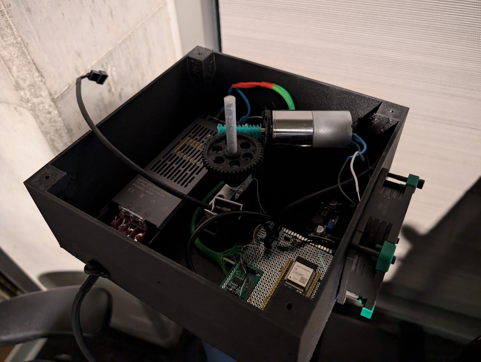
Mount the AC adapter. Insert the grommet into the AC cord hole.
Solder things up before trying to install the perfboard. Use long wires for the RC522, which we will mount to the ceiling, and the LM35, which will go up through the center column. The motor controller, BME680, and NAU7802 all go on the perfboard, as do the two Molex connectors. Prepare two long cables with ring terminals, and solder them to the perfboard to provide a 12V bus. The 12V needs go to the power pin on both Molex connectors, plus the motor controller's VM input. The ground needs hit our existing ground bus, which ought be extended to the two Molex connectors' ground pins. Connect both tach pins to the 3.3V bus with 10KΩ resistors. Take a 3.3KΩ resistor out from each, and drop wires to the MCU's tach pins. Attach 0.1nF capacitors to both resistors, and thereby link them to ground (this circuit is explained on my PC Fans page).
I2C pins are input/output open-drain lines with pullups. There is a single SDA (data) bus, to which all three I2C slaves are connected, and likewise a single SCL (clock) bus.
| J1 | J3 | ||
| Pin | Target | Pin | Target |
|---|---|---|---|
| 4 | Lower fan PWM (output) | 1 | |
| 5 | Upper fan PWM (output) | 2 | |
| 6 | Upper fan tach (input+ISR) | 42 | |
| 7 | Lower fan tach (input+ISR) | 41 | |
| 15 | 40 | RC522 interrupt (input+ISR) | |
| 16 | 39 | Motor control 1 (output) | |
| 17 | I2C SCL | 38 | |
| 18 | I2C SDA | 37 | |
| 8 | LM35 analog data (input) | 36 | |
| 3 | 35 | ||
| 46 | 0 | ||
| 9 | Motor standby (output) | 45 | |
| 10 | 48 | Motor control 2 (output) | |
| 11 | 47 | ||
| 12 | Motor PWM (output) | 21 | |
| 13 | Triac (output) | 20 | |
| 14 | 19 | ||
Prepare two wires, and solder them to the motor's terminals. Solder the other ends to the motor controller's VM out and ground. Mount the perfboard. Solder the USB-C pigtails (red and black wires; do not use the white and green) to the buck converter output and dial it to 5V. Prepare two wires with ring terminals, and solder them to the input. Mount the buck converter. Connect the USB-C male end to the MCU. Connect all four ring terminals to the output (DC) side of the AC adapter.
Smoke one if you've got one.
Cut the female end off a decent three-pronged AC cable. Strip it, revealing three wires. The black is live, the white is neutral, and the green is ground. Strip each. Put a 5A fuse inline on the live wire. Bring the three wires through the AC adapter hole. Connect the black and white cables to the 2-port side of a 2-to-4 XHF connector. Prepare four AWG 16 cables. Plug them into the 4-port side of the XHF connector. Add ring terminals to two of them, and the ground wire. I recommend then reinsulating the three terminated wires in a single sheath, and applying heat shrink. Connect the three terminated wires to the input (AC) side of the AC adapter.
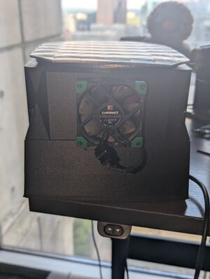
The back of the triac has a mounting hole. Looking at the front of the triac, the pins from left to right are Terminal 1, Terminal 2, and Gate. Note that the metal surrounding the mounting hole is connected to Terminal 2, and thus possibly live and a shock hazard. The triac is bidirectional across the two terminals, and controlled by the gate pin. We can control the gate with our 3.3V, and it takes only 10mA to keep it open, so we wire it directly to a GPIO. The two terminals complete the AC circuit with the heater.
Place the motor atop the motor mount, and push it forward so its rotor comes through the central hole. Use six M2 screws to mount the motor face. Push the worm gear onto the exposed rotor.
Assemble the load cell coupling and mount it to the central riser.
Mount a fan to the outside of the hotbox, facing into the chamber. Mount it with four bolts.
Insert the platform through the central hole of the hotbox, with the wide side in the hotbox, and the thin side emerging from the bottom. Mate it to the gear. Mate the gear to the bearing. Place the hotbox atop the cool chamber, so that the bearing fits into the coupling. The gear ought be touching the worm gear along a tangent. Join the chambers tightly with four M5x45 bolts.
Plug the AC cable into a live outlet. The MCU ought power on and connect to your WiFi and MQTT broker. It will be serving HTTP, and announcing itself on mDNS. It ought be consuming less than 10 watts so long as you're not actively drying (though the fans will be turned on if the cool chamber gets warm enough).
Firmware
The firmware is built using ESP-IDF in conjunction with CMake (in which it is naturally expressed), using Espressif's newest 5.4 release. I tried to minimize libraries outside of ESP-IDF itself (i.e. no WiFi etc.), coupling my code tightly to "native" ESP-IDF. I avoided Arduino SDK contrivances (i.e. pinMode() etc.) entirely; I believe these do more harm than good.
To use it, you'll need prepare a file esp32-s3/dankdryer/dryer-config.h using dryer-network-sample.h as a template. Configure your ESSID, passphrase, and MQTT broker.
All my code is in a single file: dankdryer.c
Initialization
- The single RGB LED built into the ESP32-S3 is used to indicate initialization errors (or lack thereof). Of course, this LED isn't normally visible from the outside, so it's only useful for testing. Following successful initialization, we turn it off to conserve power and LED lifetime.
- We use the NVS (non-volatile storage) subsystem for persistent storage. We keep a boot count, which is updated immediately following NVS initialization (including formatting if necessary). No errors here are considered fatal. Anything we take as configuration is persisted; any value which isn't present, or can't be read, is replaced by a default built into the code:
- Target temperature
- Exhaust fan PWM
- Intake fan PWM
- Load cell scaling parameter (determined during calibration)
- We enable the ESP32-S3's onboard thermostat.
- We set up two pins for fan 25KHz PWM (output), and two pins for fan tach (input).
- We install a hardware interrupt to count tachometer pulses.
- We initialize an I2C master bus and device.
- We probe I2C for the RC522, NAU7802, and BME680.
- We install a hardware interrupt for RC522 notifications
- We initialize the NAU7802, and configure the scaling parameter if available.
- We create an event loop, and set up WiFi with a configured ESSID and passphrase.
- We subscribe our WiFi event handler and IP event handler to all relevant events.
- Upon WiFi connection, we attempt to pull a DHCP lease.
- Upon configuration of an IP address, we attempt to connect to the configured MQTT server.
- Upon a failure at any level, we attempt to restart that level.
- If this was being built for mass production, we'd need a way to configure the network outside of code! This would probably take the form of a small display plus a physical button or two, or more likely BLE. We'd also need provide some kind of calibration interface for the load cell (the scaling parameter is specific to the cell instance). But we're not, so we don't.
Main loop
- Get current time with second resolution using RTC or wrap-corrected TSC.
- Is there an active drying end time? If not, check RC522 for RFID presence. If present:
- Attempt to read and decode RFID.
- Load optimal parameters if we know this filament type.
- Get all three temperatures.
- Are we after the active drying end time? If so:
- Ensure heater and motor are off.
- Otherwise, ensure motor is on. Is the hotbox temp below the target temp? If so:
- Ensure heater is on. Otherwise, ensure heater is off.
- Get humidity, pressure, and VOC count from BME680.
- Request the average of five consecutive measurements from NAU7802.
- Calculate fan RPMs using tach pulse count and time delta.
- Report all measurements, configuration elements, and drying end time via MQTT.
One annoying thing here, as you might have picked up on while reading the pseudocode, is that immediately following the end of a drying operation, we're going to reread the RFID of the spool we just dried, and preload its optimal drying parameters. We don't kick off a dry based on RFID read, but it's still not quite what we want.
Dry request
A dry request is indicated by specifying a number of seconds to dry. This is converted into a realtime, which becomes the active drying end time. This requires taking a lock. We allow the main loop to take care of the rest, so that setting the expiry time is the only need for mutual exclusion. An ongoing dry can be cancelled by making a request for zero second in the future (this is not a special case, but rather falls naturally out of the main loop's behavior).
Reducing the BOM
- The Geartisan motor ran $15 off Amazon. Pretty much any other brushed DC motor would cut costs substantially.
- The motor controller can probably be replaced with a power MOSFET plus a flyback diode.
- We could get away with a much cheaper AC adapter.
- Using SMT components together with a custom PCB would cut electronics costs (for instance, rather than a discrete 12V->5V buck converter, we'd just roll our own directly on the PCB), and also lead to a much cleaner interior and fewer assembly failures.
- The Noctua fans are premium; we don't even run the fans very hard, and could maintain silent operation with cheaper ones.
Getting into the realm of diminishing returns, the XHF connector runs less than a dollar, but could still be replaced with soldered splicing (effectively free) or a solderfree heat connector (cents).
Replacing the buck converter with voltage dividers would waste significant power (generating heat in the process), so I don't like that idea.
Conclusions and lessons learned
- Don't use the Arduino high-level libraries unless you need the portability.
- I ought have used esp-idf from the beginning, and eventually moved to it.
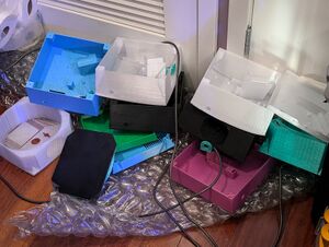
- I should have done my models so that I could test small parts more easily. Look at all the design iterations which didn't make it here to be with us today.
- For instance, all the mounts ought have been their own printings. That way I could check their geometries against the electronics without needing respin the entire chamber. Since I'm already screwing the electronics into the mounts, it's no extra hit to screw the mounts into the chamber.
- Read the datasheets. If it doesn't have a datasheet, don't buy it!
- Always do a PCB (this will be a future blog post).
- My value to a terrorist organization increases with every project.
- Nothing is simple, but everything is easy.
Render
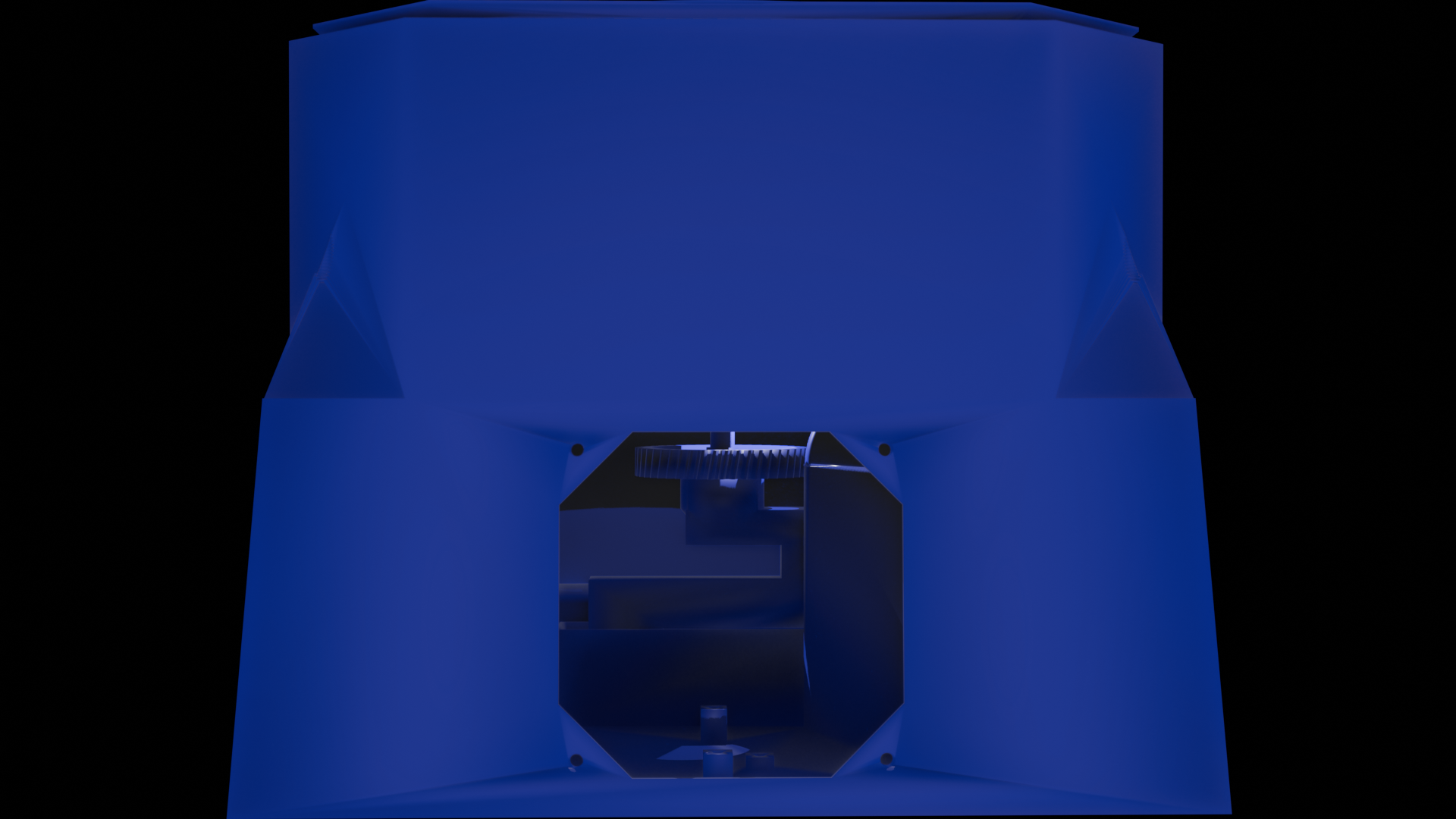
Should you ever need correct your own high opinion of your intelligence, I've found blender to be a perfect cure. It terrifies me every time I open it. After an hour or two of fucking around with cameras and light sources, I managed to generate this sexy render (on the right) from my unified STLs (on the left):
previously: "questions cheerfully answered" 2024-07-02

