Check out my first novel, midnight's simulacra!
ESP8266: Difference between revisions
No edit summary Tags: mobile web edit mobile edit |
Tags: mobile web edit mobile edit |
||
| (10 intermediate revisions by the same user not shown) | |||
| Line 1: | Line 1: | ||
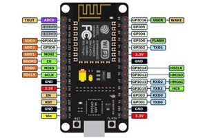
[[File:Esp8266nodemcu.jpg|right|thumb|Pinout for the NodeMCU v1]] | |||
A series of 32-bit microcontroller units from [https://www.espressif.com/ Espressif], followed by the [[ESP32]]. The first generation of the NodeMCU SoC was based around ESP8266. | A series of 32-bit microcontroller units from [https://www.espressif.com/ Espressif], followed by the [[ESP32]]. The first generation of the NodeMCU SoC was based around ESP8266. | ||
== | ==Hardware== | ||
* There is only one (10-bit) ADC, and it reports values between [0, 1], ''not'' [0, 3.3]. This is not a scaling--the input voltage should not exceed 1V. | A Tensilica Diamond Standard 106Micro runs the Xtensa instruction set at 80MHz by default, and can be run at 160MHz. 32KB of code memory and 80KB of data are available to the user. There is no cache. IEEE 802.11 b/g/n support is available in AP, STA, and monitor modes. | ||
* | |||
===GPIO=== | |||
* 17 bidirectional, non-inverting, tristate GPIO pins, with input and output buffer registers. | |||
** Pullup and pulldown resistors available on all pins | |||
** Pins can be set high-impedence | |||
** Edge- and level-triggered interrupts available on all pins | |||
===PWM=== | |||
Four PWM channels on pins 10, 13, 9, and 16: | |||
{| class="wikitable" | |||
! Pin name !! Pin number !! IO Function !! Name | |||
|- | |||
| MTDI || 10 || IO12 || PWM0 | |||
|- | |||
| MTDO || 13 || IO15 || PWM1 | |||
|- | |||
| MTMS || 9 || IO14 || PWM2 | |||
|- | |||
| GPIO4 || 16 || IO4 || PWM3 | |||
|- | |||
|} | |||
The minimum PWM resolution is 45ns (an approximate PWM clock of 22.72MHz), supporting 14 bits of PWM resolution at 1KHz. Active PWM prevents the system from entering Deep Sleep mode, and entering Light Sleep will disrupt PWM. | |||
Unfortunately, the Espressif-provided PWM API only supports frequencies up to 1KHz. Libraries such as [https://github.com/StefanBruens/ESP8266_new_pwm ESP8266_new_pwm] can exceed these limitations. It ought be possible to achieve 7-bit PWM at the 25KHz required for [[PC Fans|pc fans]]. | |||
===ADC=== | |||
There is only one (10-bit) ADC, and it reports values between [0, 1], ''not'' [0, 3.3]. This is not a scaling--the input voltage should not exceed 1V. The NodeMCU changes this significantly: | |||
* The NodeMCU [https://www.electronicwings.com/nodemcu/nodemcu-adc-with-arduino-ide applies a divider network] to scale the 3.3V down to 1V. This usefully allows supplying 3.3V to the external device. | |||
* On the NodeMCU, this ADC can read the battery voltage instead of a connected external device. This is set in firmware. | |||
* If the ADC is left unconnected, V<sub>CC</sub> can be read using <tt>ESP.getVcc()</tt>. Before calling this function, <tt>ADC_MODE(ADC_TOUT)</tt> (for external voltage) or <tt>ADC_MODE(ADC_VCC)</tt> (for system voltage) must be called. | |||
==External links== | ==External links== | ||
* [https://en.wikipedia.org/wiki/ESP8266 ESP8266] on Wikipedia | * [https://en.wikipedia.org/wiki/ESP8266 ESP8266] on Wikipedia | ||
* [https://www.espressif.com/sites/default/files/documentation/esp8266-technical_reference_en.pdf ESP8266 Technical Reference] | |||
[[CATEGORY: Hardware]] | [[CATEGORY: Hardware]] | ||
Latest revision as of 07:12, 26 November 2022

A series of 32-bit microcontroller units from Espressif, followed by the ESP32. The first generation of the NodeMCU SoC was based around ESP8266.
Hardware
A Tensilica Diamond Standard 106Micro runs the Xtensa instruction set at 80MHz by default, and can be run at 160MHz. 32KB of code memory and 80KB of data are available to the user. There is no cache. IEEE 802.11 b/g/n support is available in AP, STA, and monitor modes.
GPIO
- 17 bidirectional, non-inverting, tristate GPIO pins, with input and output buffer registers.
- Pullup and pulldown resistors available on all pins
- Pins can be set high-impedence
- Edge- and level-triggered interrupts available on all pins
PWM
Four PWM channels on pins 10, 13, 9, and 16:
| Pin name | Pin number | IO Function | Name |
|---|---|---|---|
| MTDI | 10 | IO12 | PWM0 |
| MTDO | 13 | IO15 | PWM1 |
| MTMS | 9 | IO14 | PWM2 |
| GPIO4 | 16 | IO4 | PWM3 |
The minimum PWM resolution is 45ns (an approximate PWM clock of 22.72MHz), supporting 14 bits of PWM resolution at 1KHz. Active PWM prevents the system from entering Deep Sleep mode, and entering Light Sleep will disrupt PWM.
Unfortunately, the Espressif-provided PWM API only supports frequencies up to 1KHz. Libraries such as ESP8266_new_pwm can exceed these limitations. It ought be possible to achieve 7-bit PWM at the 25KHz required for pc fans.
ADC
There is only one (10-bit) ADC, and it reports values between [0, 1], not [0, 3.3]. This is not a scaling--the input voltage should not exceed 1V. The NodeMCU changes this significantly:
- The NodeMCU applies a divider network to scale the 3.3V down to 1V. This usefully allows supplying 3.3V to the external device.
- On the NodeMCU, this ADC can read the battery voltage instead of a connected external device. This is set in firmware.
- If the ADC is left unconnected, VCC can be read using ESP.getVcc(). Before calling this function, ADC_MODE(ADC_TOUT) (for external voltage) or ADC_MODE(ADC_VCC) (for system voltage) must be called.
External links
- ESP8266 on Wikipedia
- ESP8266 Technical Reference