| [ Team LiB ] |


|
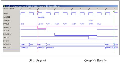
Serial Bus TopologyPCI Express's serial bus topology represents a challenge for test and debug development tools. In a parallel bus, as the name identifies, all of the protocol signals associated with data transfer are simultaneously presented and act in parallel. Developers can see bus signals and interpret bus conditions by just capturing and viewing raw bus signals with a relatively simple development tool. An example of simultaneously active signals on a PCI bus (Captured by a Catalyst analyzer) is depicted in Figure A-1. In this example the user can see the individual signals which each have their own specific meaning. When FRAME# is asserted (low), it indicates that the initiator is requesting a data transfer. CBE = 0x0010, indicating that this transfer is an IO read and TRDY# = 0, indicating the data transfer of 0x99h completed. Figure A-1. PCI Parallel Bus Start and End of a Transaction Easily Identified
Also, when all bus signals (except clock) are high it indicates that the bus is in the idle state. Unlike parallel buses, the status of serial buses cannot easily be identified by monitoring the individual bus signals. A more complex process is required for monitoring and interpretation of Serial buses such as PCI Express, for the following reasons:
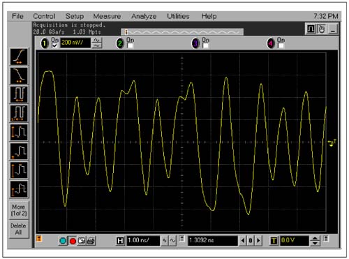
Converting binary bits into a meaningful interpretation of all these layers requires an advanced and dedicated tool, beyond the capability of many low level monitoring development tools. Figure A-2 indicates a data capture of a PCI Express bus transaction on a scope in its most primitive form. Comparing to the PCI bus, it would be impossible to interpret what is occurring on this serial bus. Figure A-2. PCI Express Serial Bit Stream
It should be noted that the PCI Express transmit/receive signals each consist of a differential signal pair and the sample shown here display the output of such a differential signal pair.  |
| [ Team LiB ] |
|