| [ Team LiB ] |


|
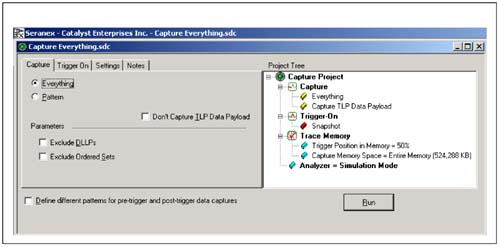
Setting Up the Analyzer, Capturing and TriggeringFigure A-4 on page 966 and Figure A-5 on page 967 indicate various setups for capturing and triggering on possible PCI Express bus states. Figure A-4. Capturing All Patterns on PCI Express
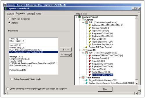
Figure A-5. Specific Trigger Definition for Upstream or Downstream Pair
To review the complete menus and features you may download and try the software from the Catalyst web site (www.getcatalyst.com). Figure A-4 provides a default setup for capturing anything on the bus and indicates whether or not there is any data transfer or the bus is in an idle state. Any transactions would be captured and displayed with all details included. Further triggering selections will allow users to fully qualify the bus data and transaction type and to see exactly what sort of request and response is communicated between the agents on the bus. Figure A-5 on page 967 shows a data capture setup for capturing all TLP packets on both buses and to trigger when a TLP memory read to address range 0x00FE8DXX….XX occurs, but only when it is initiated in the downstream bus. Sequential triggering also allows the user to trigger on patterns only after a certain set of events has occurred (as defined by the user).  |
| [ Team LiB ] |
|