| [ Team LiB ] |


|
The History Multi-Processor Implementations Using PCITo better understand the implementation proposed for PCI Express, one needs to first understand the PCI implementation. PCI was originally defined in 1992 for personal computers. Because of the nature of PCs at that time, the protocol architects did not anticipate the need for multiprocessors. Therefore, they designed the system assuming that the host processor would enumerate the entire memory space. Obviously, if another processor is added, the system operation would fail as both processors would attempt to service the system requests. 1Several methodologies were subsequently invented to accommodate the requirement for multiprocessor capabilities using PCI. The most popular implementation, and the one discussed in this paper for PCI Express, is the use of non-transparent bridging between the processing subsystems to isolate their memory spaces.[1]
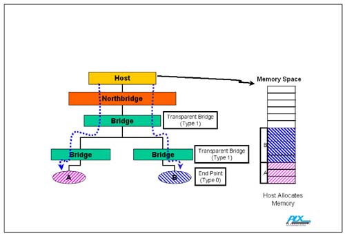
Because the host does not know the system topology when it is first powered up or reset, it must perform discovery to learn what devices are present and then map them into the memory space. To support standard discovery and configuration software, the PCI specification defines a standard format for Control and Status Registers (CSRs) of compliant devices. The standard PCI-to-PCI bridge CSR header, called a Type 1 header, includes primary, secondary and subordinate bus number registers that, when written by the host, define the CSR addresses of devices on the other side of the bridge. Bridges that employ a Type 1 CSR header are called transparent bridges. A Type 0 header is used for endpoints. A Type 0 CSR header includes base address registers (BARs) used to request memory or I/O apertures from the host. Both Type 1 and Type 0 headers include a class code register that indicates what kind of bridge or endpoint is represented, with further information available in a subclass field and in device ID and vendor ID registers. The CSR header format and addressing rules allow the processor to search all the branches of a PCI hierarchy, from the host bridge down to each of its leaves, reading the class code registers of each device it finds as it proceeds, and assigning bus numbers as appropriate as it discovers PCI-to-PCI bridges along the way. At the completion of discovery, the host knows which devices are present and the memory and I/O space each device requires to function. These concepts are illustrated in Figure C-1. Figure C-1. Enumeration Using Transparent Bridges
 |
| [ Team LiB ] |
|