| [ Team LiB ] |


|
Implementing Multi-host/Intelligent Adapters in PCI Express Base SystemsUp to this point, our discussions have been limited to one processor with one memory space. As technology progressed, system designers began developing end points with their own native processors built in. The problem that this caused was that both the host processor and the intelligent adapter would, upon power up or reset, attempt to enumerate the entire system, causing system conflict and ultimately a non-functional system.[2]
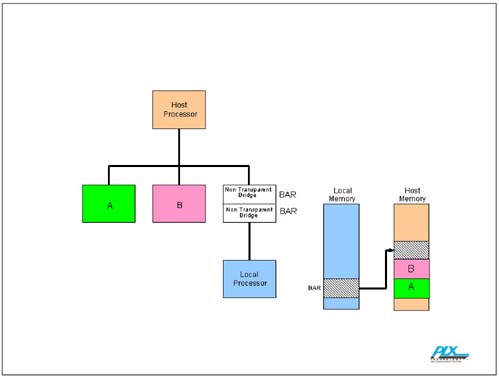
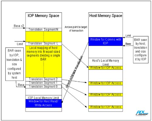
To get around this, architects designed non-transparent bridges. A non-transparent PCI-to-PCI Bridge, or PCI Express-to-PCI Express Bridge, is a bridge that exposes a Type 0 CSR header on both sides and forwards transactions from one side to the other with address translation, through apertures created by the BARs of those CSR headers. Because it exposes a Type 0 CSR header, the bridge appears to be an endpoint to discovery and configuration software, eliminating potential discovery software conflicts. Each BAR on each side of the bridge creates a tunnel or window into the memory space on the other side of the bridge. To facilitate communication between the processing domains on each side, the non-transparent bridge also typically includes doorbell registers to send interrupts from each side of the bridge to the other, and scratchpad registers accessible from both sides. A non-transparent bridge is functionally similar to a transparent bridge in that both provide a path between two independent PCI buses (or PCI Express links). The key difference is that when a non-transparent bridge is used, devices on the downstream side of the bridge (relative to the system host) are not visible from the upstream side. This allows an intelligent controller on the downstream side to manage the devices in its local domain, while at the same time making them appear as a single device to the upstream controller. The path between the two buses allows the devices on the downstream side to transfer data directly to the upstream side of the bus without directly involving the intelligent controller in the data movement. Thus transactions are forwarded across the bus unfettered just as in a PCI-to-PCI Bridge, but the resources responsible are hidden from the host, which sees a single device. Because we now have two memory spaces, the PCI Express system needs to translate addresses of transactions that cross from one memory space to the other. This is accomplished via Translation and Limit Registers associated with the BAR. See "Address Translation" on page 1013 for a detailed description; Figure C-2 on page 1004 provides a conceptual rendering of Direct Address Translation. Address translation can be done by Direct Address Translation (essentially replacement of the data under a mask), table lookup, or by adding an offset to an address. Figure C-3 on page 1005 shows Table Lookup Translation used to create multiple windows spread across system memory space for packet originated in a local I/O processor's domain, as well as Direct Address Translation used to create a single window in the opposite direction. Figure C-2. Direct Address Translation
Figure C-3. Look Up Table Translation Creates Multiple Windows
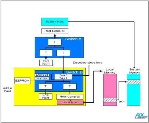
Example: Implementing Intelligent Adapters in a PCI Express Base SystemIntelligent adapters will be pervasive in PCI Express systems, and will likely be the most widely used example of systems with "multiple processors". Figure C-4 on page 1006 illustrates how PCI Express systems will implement intelligent adapters. The system diagram consists of a system host, a root complex (the PCI Express version of a Northbridge), a three port switch, an example endpoint, and an intelligent add-in card. Similar to the system architecture, the add-in card contains a local host, a root complex, a three port switch, and an example endpoint. However we should note two significant differences: the intelligent add-in card contains an EEPROM, and one port of the switch contains a back to back non-transparent bridge. Figure C-4. Intelligent Adapters in PCI and PCI Express Systems
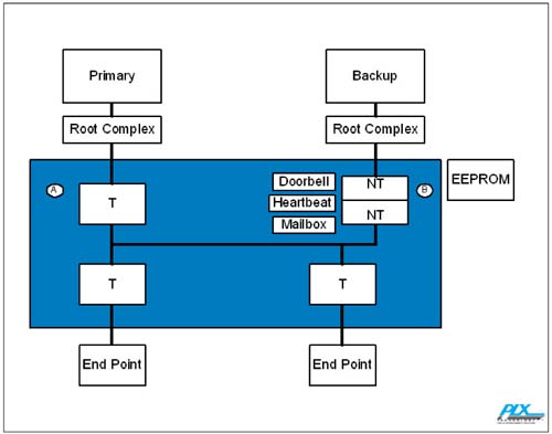
Upon power up, the system host will begin enumerating to determine the topology. It will pass through the Root Complex and enter the first switch (Switch A). Upon entering the topmost port, it will see a transparent bridge, so it will know to continue to enumerate. The host will then poll the leftmost port and, upon finding a Type 0 CSR header, will consider it an endpoint and explore no deeper along that branch of the PCI hierarchy. The host will then use the information in the endpoint's CSR header to configure base and limit registers in bridges and BARs in endpoints to complete the memory map for this branch of the system. The host will then explore the rightmost port of Switch A and read the CSR header registers associated with the top port of Switch B. Because this port is a non-transparent bridge, the host finds a Type 0 CSR header. The host processor therefore believes that this is an endpoint and explores no deeper along that branch of the PCI hierarchy. The host reads the BARs of the top port of Switch B to determine the memory requirements for windows into the memory space on the other side of the bridge. The memory space requirements can be preloaded from an EEPROM into the BAR Setup Registers of Switch B's non-transparent port or can be configured by the processor that is local to Switch B prior to allowing the system host to complete discovery. Similar to the host processor power up sequence, the local host will also begin enumerating its own system. Like the system host processor, it will allocate memory for end points and continue to enumerate when it encounters a transparent bridge. When the host reaches the topmost port of Switch B, it sees a non-transparent bridge with a Type 0 CSR header. Accordingly, it reads the BARs of the CSR header to determine the memory aperture requirements, then terminates discovery along this branch of its PCI tree. Again, the memory aperture information can be supplied by an EEPROM, or by the system host. Communication between the two processor domains is achieved via a mailbox system and doorbell interrupts. The doorbell facility allows each processor to send interrupts to the other. The mailbox facility is a set of dual ported registers that are both readable and writable by both processors. Shared memory mapped mechanisms via the BARs may also be used for inter-processor communication. Example: Implementing Host Failover in a PCI Express SystemFigure C-5 on page 1008 illustrates how most PCI Express systems will implement host failover. The primary host processor in this illustration is on the left side of the diagram, with the backup host on the right side of the diagram. Like most systems with which we are familiar, the host processor connects to a root complex. In turn, the root complex routes its traffic to the switch. In this example, the switch has two ports to end points in addition to the upstream port for the primary host we have just described. Furthermore, this system also has another processor, which is connected to the switch via another root complex. Figure C-5. Host Failover in PCI and PCI Express Systems
The switch ports to both processors need to be configurable to behave either as a transparent bridge or a non-transparent bridge. An EEPROM or strap pins on the switch can be used to initially bootstrap this configuration. Under normal operation, upon power up, the primary host begins to enumerate the system. In our example, as the primary host processor begins its discovery protocol through the fabric, it discovers the two end points, and their memory requirements, by sizing their BARs. When it gets to the upper right port, it finds a Type 0 CSR header. This signifies to the primary host processor that it should not attempt discovery on the far side of the associated switch port. As in the previous example, the BARs associated with the non-transparent switch port may have been configured by EEPROM load prior to discovery or might be configured by software running on the local processor. Again, similar to the previous example, the backup processor powers up and begins to enumerate. In this example, the backup processor chipset consists of the root complex and the backup processor only. It discovers the non-transparent switch port and terminates its discovery there. It is keyed by EEPROM loaded Device ID and Vendor ID registers to load an appropriate driver. During the course of normal operation, the host processor performs all of its normal duties as it actively manages the system. In addition, it will send messages to the backup processor called heartbeat messages. Heartbeat messages are indications of the continued good health of the originating processor. A heartbeat message might be as simple as a doorbell interrupt assertion, but typically would include some data to reduce the possibility of a false positive. Checkpoint and journal messages are alternative approaches to providing the backup processor with a starting point, should it need to take over. In the journal methodology, the backup is provided with a list or journal of completed transactions (in the application specific sense, not in the sense of bus transactions). In the checkpoint methodology, the backup is periodically provided with a complete system state from which it can restart if necessary. The heartbeat's job is to provide the means by which the backup processor verifies that the host processor is still operational. Typically this data provides the latest activities and the state of all the peripherals. If the backup processor fails to receive timely heartbeat messages, it will begin assuming control. One of its first tasks is to demote the primary port to prevent the failed processor from interacting with the rest of the system. This is accomplished by reprogramming the CSRs of the switch using a memory mapped view of the switch's CSRs provided via a BAR in the non-transparent port. To take over, the backup processor reverses the transparent/non-transparent modes at both its port and the primary processor's port and takes down the link to the primary processor. After cleaning up any transactions left in the queues or left in an incomplete state as a result of the host failure, the backup processor reconfigures the system so that it can serve as the host. Finally, it uses the data in the checkpoint or journal messages to restart the system. Example: Implementing Dual Host in a PCI Express Base SystemFigure C-6 on page 1010 illustrates how PCI Express systems might implement a dual host system[3]. In this example, the leftmost blocks are a typically complete system, with the rightmost blocks being a separate subsystem. As previously discussed, connecting the leftmost and rightmost diagram is a set of non-transparent bridges.
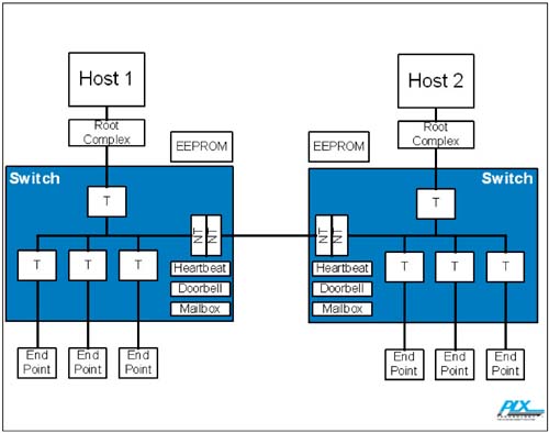
Figure C-6. Dual Host in a PCI and PCI Express System
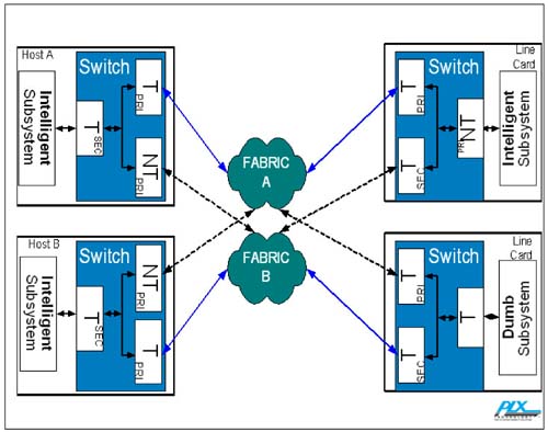
Upon power up, both processors will begin enumerating. As before, the hosts will search out the endpoints by reading the CSR and then allocate memory appropriately. When the hosts encounter the non-transparent bridge port in each of their private switches, they will assume it is an endpoint and, using the data in the EEPROM, allocate resources. Both systems will use the doorbell and mailbox registers described above to communicate with each other. 2The dual-host system model may be extended to a fully redundant dual star system by using additional switches to dual-port the hosts and line cards into a redundant fabric as shown in Figure C-7 on page 1012. This is particularly attractive to vendors who employ chassis based systems for their flexibility, scalability and reliability. Figure C-7. Dual-Star Fabric
Two host cards are shown. Host A is the primary host of Fabric A and the secondary host of Fabric B. Similarly, Host B is the primary host of Fabric B and the secondary host of Fabric A. Each host is connected to the fabric it serves via a transparent bridge/switch port and to the fabric for which it provides only backup via a non-transparent bridge/switch port. These non-transparent ports are used for host-to-host communications and also support cross-domain peer-to-peer transfers where address maps do not allow a more direct connection.  |
| [ Team LiB ] |
|