| [ Team LiB ] |


|
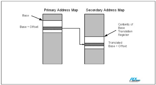
Address TranslationThis section provides an in-depth description of how systems that use non-transparent bridges communicate using address translation. We provide details about the mechanism by which systems determine not only the size of the memory allocated, but also about how memory pointers are employed. Implementations using both Direct Address Translation as well as Lookup Table Based Address Translation are discussed. By using the same standardized architectural implementation of non transparent bridging popularized in the PCI paradigm into the PCI Express environment, interconnect vendors can speed market adoption of PCI Express into markets requiring intelligent adapters, host failover and multihost capabilities. The transparent bridge uses base and limit registers in I/O space, non-prefetchable memory space, and prefetchable memory space to map transactions in the downstream direction across the bridge. All downstream devices are required to be mapped in contiguous address regions such that a single aperture in each space is sufficient. Upstream mapping is done via inverse decoding relative to the same registers. A transparent bridge does not translate the addresses of forwarded transactions/packets. The non-transparent bridges use the standard set of BARs in their Type 0 CSR header to define apertures into the memory space on the other side of the bridge. There are two sets of BARs: one on the Primary side and one on the Secondary. BARs define resource apertures that allow the forwarding of transactions to the opposite (other side) interface. For each BAR bridge there exists a set of associated control and setup registers usually writable from the other side of the bridge. Each BAR has a "setup" register, which defines the size and type of its aperture, and an address translation register. Some bars also have a limit register that can be used to restrict its aperture's size. These registers need to be programmed prior to allowing access from outside the local subsystem. This is typically done by software running on a local processor or by loading the registers from EEPROM. In PCI Express, the Transaction ID fields of packets passing through these apertures are also translated to support Device ID routing. These Device IDs are used to route completions to non-posted requests and ID routed messages. The transparent bridge forwards CSR transactions in the downstream direction according to the secondary and subordinate bus number registers, converting Type 1 CSRs to Type 0 CSRs as required. The non-transparent bridge accepts only those CSR transactions addressed to it and returns an unsupported request response to all others. Direct Address TranslationThe addresses of all upstream and downstream transactions are translated (except BARs accessing CSRs). With the exception of the cases in the following two sections, addresses that are forwarded from one interface to the other are translated by adding a Base Address to their offset within the BAR that they landed in as seen in Figure C-8 on page 1014. The BAR Base Translation Registers are used to set up these base translations for the individual BARs. Figure C-8. Direct Address Translation
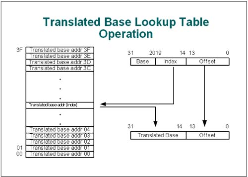
Lookup Table Based Address TranslationFollowing the de facto standard adopted by the PCI community, PCI Express should provide several BARs for the purposes of allocating resources. All BARs contain the memory allocation; however, in accordance with PCI industry conventions, BAR 0 contains the CSR information whereas BAR1 contains I/O information, BAR 2 and BAR 3 are utilized for Lookup Table Based Translation. BAR 4 and BAR 5 are utilized for Direct Address Translations. On the secondary side, BAR3 uses a special lookup table based address translation for transactions that fall inside its window as seen in Figure C-9 on page 1015. The lookup table provides more flexibility in secondary bus local addresses to primary bus addresses. The location of the index field with the address bus is programmable to adjust aperture size. Figure C-9. Lookup Table Based Translation
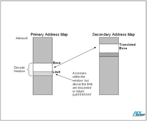
Downstream BAR Limit RegistersThe two downstream BARs on the primary side (BAR2/3 and BAR4/5) also have Limit registers, programmable from the local side, to further restrict the size of the window they expose, as seen in Figure C-10 on page 1016. BARs can only be assigned memory resources in "power of two" granularity. The limit registers provide a means to obtain better granularity by "capping" the size of the BAR within the "power of two" granularity. Only transactions below the Limit registers are forwarded to the secondary bus. Transactions above the limit are discarded or return 0xFFFFFFFF, or a master abort equivalent packet, on reads. Figure C-10. Use of Limit Register
Forwarding 64bit Address Memory TransactionsCertain BARs can be configured to work in pairs to provide the base address and translation for transactions containing 64-bit addresses. Transactions that hit within these 64-bit BARs are forwarded using Direct Address Translation. As in the case of 32 bit transactions, when a memory transaction is forwarded from the primary to the secondary bus, the primary address can be mapped to another address in the secondary bus domain. The mapping is performed by substituting a new base address for the base of the original address. A 64-bit BAR pair on the system side of the bridge is used to translate a window of 64-bit addresses in packets originated on the system side of the bridge down below 232 in local space.  |
| [ Team LiB ] |
|