The PCI Express Lock Protocol
The only source of lock supported by PCI Express is the system processor, and, as a consequence, the source of all locked operations in PCI Express is the Root Complex (acting as the processor's surrogate). A locked operation is performed between a Root Complex downstream port and the PCI Express downstream port to which the targeted legacy device is attached. In most systems, the legacy device is typically a PCI Express-to-PCI or PCI Express-to-PCI-X bridge. Only one locked sequence at a time is supported for a given hierarchical path.
PCI Express limits locked transactions to Traffic Class 0 and Virtual Channel 0. All transactions with TC values other than zero that are mapped to a VC other than zero are permitted to traverse the fabric without regard to the locked operation. All transactions that are mapped to VC0 are subject to the lock rules described in this appendix. The discussion of the locked protocol in this appendix presumes that all transactions have been assigned to TC0 (unless otherwise indicated).
Lock Messages — The Virtual Lock Signal
PCI Express defines the following transactions that, together, act as a virtual wire that replaces the PCI LOCK# signal.
Memory Read Lock Request (MRdLk) —
Originates a locked sequence. The first MRdLk transaction blocks other requests from reaching the target device. One or more of these locked read requests may be issued during the sequence.
Memory Read Lock Completion with Data (CplDLk) —
Returns data and confirms that the path to the target is locked. A successful read Completion that returns data for the first Memory Read Lock request results in the path between the Root Complex and the target device being locked. That is, transactions traversing the same path from other ports are blocked from reaching either the root port or the target port. Transactions being routed in buffers for VC1-VC7 are unaffected by the lock.
Memory Read Lock Completion without Data (CplLK) —
A Completion without a data payload indicates that the lock sequence cannot complete currently and the path remains unlocked.
Unlock Message —
An unlock message is issued by the Root Complex from the locked root port. This message unlocks the path between the root port and the target port.
The Lock Protocol Sequence — an Example
This section explains the PCI Express lock protocol by example. The example includes the following devices:
The Root Complex that initiates the Locked transaction series on behalf of the host processor. A Switch in the path between the root port and targeted legacy endpoint. A PCI Express-to-PCI Bridge in the path to the target. The target PCI device who's Device Driver initiated the locked RMW. A PCI Express endpoint is included to describe Switch behavior during lock.
In this example, the locked operation completes normally. The steps that occur during the operation are described in the two sections that follow.
The Memory Read Lock Operation
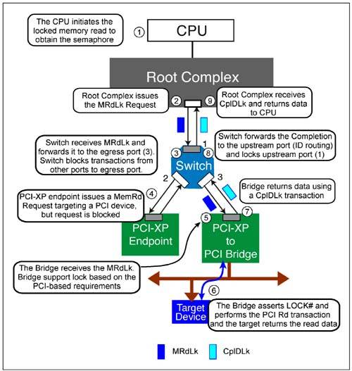
Figure E-1 on page 1037 illustrates the first step in the Locked transaction series (i.e., the initial memory read to obtain the semaphore):
The CPU initiates the locked sequence (a Locked Memory Read) as a result of a driver executing a locked RMW instruction that targets a PCI target. The Root Port issues a Memory Read Lock Request from port 2. The Root Complex is always the source of a locked sequence. The Switch receives the lock request on its upstream port and forwards the request to the target egress port (3). The switch, upon forwarding the request to the egress port, must block all requests from ports other than the ingress port (1) from being sent from the egress port. A subsequent peer-to-peer transfer from the illustrated PCI Express endpoint to the PCI bus (switch port 2 to switch port 3) would be blocked until the lock is cleared. Note that the lock is not yet established in the other direction. Transactions from the PCI Express endpoint could be sent to the Root Complex. The Memory Read Lock Request is sent from the Switch's egress port to the PCI Express-to-PCI Bridge. This bridge will implement PCI lock semantics (See the MindShare book entitled PCI System Architecture, Fourth Edition, for details regarding PCI lock). The bridge performs the Memory Read transaction on the PCI bus with the PCI LOCK# signal asserted. The target memory device returns the requested semaphore data to the bridge. Read data is returned to the Bridge and is delivered back to the Switch via a Memory Read Lock Completion with Data (CplDLk). The switch uses ID routing to return the packet upstream towards the host processor. When the CplDLk packet is forwarded to the upstream port of the Switch, it establishes a lock in the upstream direction to prevent traffic from other ports from being routed upstream. The PCI Express endpoint is completely blocked from sending any transaction to the Switch ports via the path of the locked operation. Note that transfers between Switch ports not involved in the locked operation would be permitted (not shown in this example). Upon detecting the CplDLk packet, the Root Complex knows that the lock has been established along the path between it and the target device, and the completion data is sent to the CPU.
Read Data Modified and Written to Target and Lock Completes
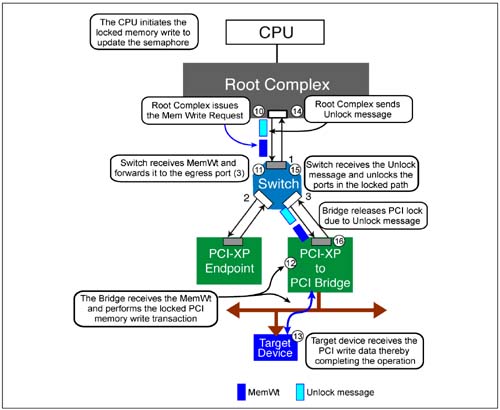
The device driver receives the semaphore value, alters it, and then initiates a memory write to update the semaphore within the memory of the legacy PCI device. Figure E-2 on page 1038 illustrates the write sequence followed by the Root Complex's transmission of the Unlock message that releases the lock:
The Root Complex issues the Memory Write Request across the locked path to the target device. The Switch forwards the transaction to the target egress port (3). The memory address of the Memory Write must be the same as the initial Memory Read request. The bridge forwards the transaction to the PCI bus. The target device receives the memory write data. Once the Memory Write transaction is sent from the Root Complex, it sends an Unlock message to instruct the Switches and any PCI/PCI-X bridges in the locked path to release the lock. Note that the Root Complex presumes the operation has completed normally (because memory writes are posted and no Completion is returned to verify success). The Switch receives the Unlock message, unlocks its ports and forwards the message to the egress port that was locked to notify any other Switches and/or bridges in the locked path that the lock must be cleared. Upon detecting the Unlock message, the bridge must also release the lock on the PCI bus.
Notification of an Unsuccessful Lock
A locked transaction series is aborted when the initial Memory Read Lock Request receives a Completion packet with no data (CplLk). This means that the locked sequence must terminate because no data was returned. This could result from an error associated with the memory read transaction, or perhaps the target device is busy and cannot respond at this time.
|

