| [ Team LiB ] |


|
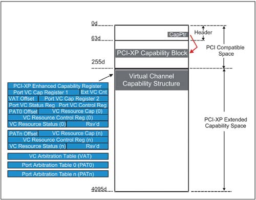
Traffic Classes and Virtual ChannelsDuring initialization a PCI Express device-driver communicates the levels of QoS that it desires for its transactions, and the operating system returns TC values that correspond to the QoS requested. The TC value ultimately determines the relative priority of a given transaction as it traverses the PCI Express fabric. Two hardware mechanisms provide guaranteed isochronous bandwidth and differentiated services: These arbitration mechanisms use VC numbers to manage transaction priority. System configuration software must assign VC IDs and set up the association between the traffic class assigned to a transaction and the virtual channel to be used when traversing each link. This is done via VC configuration registers mapped within the extended configuration address space. The list of these registers and their location within configuration space is illustrated in Figure 6-2. Figure 6-2. VC Configuration Registers Mapped in Extended Configuration Address Space
The TC value is carried in the transaction packet header and can contain one of eight values (TC0-TC7). TC0 must be implemented by all PCI Express devices and the system makes a "best effort" when delivering transactions with the TC0 label. TC values of TC1-TC7 are optional and provide seven levels of arbitration for differentiating between packet streams that require varying amounts of bandwidth. Similarly, eight VC numbers (VC0-VC7) are specified, with VC0 required and VC1-VC7 optional. ("VC Assignment and TC Mapping" on page 258 discusses VC initialization). Note that TC0 is hardwired to VC0 in all devices. If configuration software is not PCI Express aware all transactions will use the default TC0 and VC0; thereby eliminating the possibility of supporting differentiated services and isochronous transactions. Furthermore, the specification requires some transaction types to use TC0/VC0 exclusively:
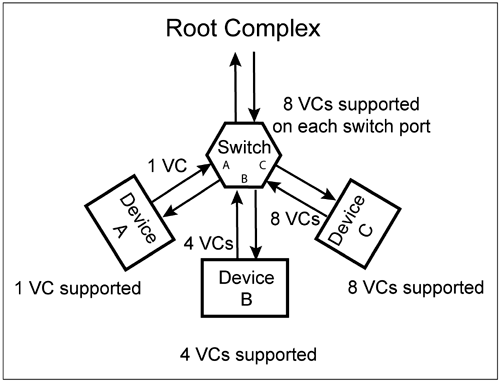
VC Assignment and TC MappingConfiguration software designed for PCI Express sets up virtual channels for each link in the fabric. Recall that the default TC and VC assignments following Cold Reset will be TC0 and VC0, which is used when the configuration software is not PCI Express aware. The number of virtual channels used depends on the greatest capability shared by the two devices attached to a given link. Software assigns an ID for each VC and maps one or more TCs to each. Determining the Number of VCs to be UsedSoftware checks the number of VCs supported by the devices attached to a common link and assigns the greatest number of VCs that both devices have in common. For example, consider the three devices attached to the switch in Figure 6-3 on page 259. In this example, the switch supports all 8 VCs on each of its ports; while Device A supports only the default VC, Device B supports 4 VC s, and Device C support 8 VCs. When configuring VCs for each link, software determines the maximum number of VCs supported by both devices at each end of the link and assigns that number to both devices. The VC assignment applies to transactions flowing across a link in both directions. Figure 6-3. The Number of VCs Supported by Device Can Vary
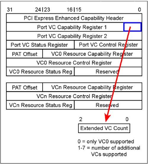
Note that even though switch port A supports all 8 VCs Device A supports a single VC, leaving 7 VCs unused within switch port A. Similarly, 4 VCs are used by switch port B. Software of course configures and enables all 8 VCs within switch port C. Configuration software determines the maximum number of VCs supported by each port interface by reading its Extended VC Count field contained within the "Virtual Channel Capability" registers. The smaller of the two values governs the maximum number of VCs supported by this link for both transmission and reception of transactions. Figure 6-4 on page 260 illustrates the location and format of the Extended VC Count field. Software may restrict the number of VCs configured and enabled to fewer than actually allowed. This may be done to achieve the QoS desired for a given platform or application. Figure 6-4. Extended VCs Supported Field
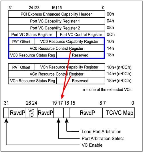
Assigning VC Numbers (IDs)Configuration software must assign VC numbers or IDs to each of the virtual channels, except VC0 which is always hardwired. As illustrated in Figure 6-5 on page 261, the VC Capabilities registers include 3 DWs used for configuring each VC. The first set of registers (starting at offset 10h) always applies to VC0. The Extended VCs Count field (described above) defines the number of additional VC register sets implemented by this port, each of which permits configuration of an additional VC. Note that these register sets are mapped in configuration space directly following the VC0 registers. The mapping is expressed as an offset from each of the three VC0 DW registers:
Figure 6-5. VC Resource Control Register
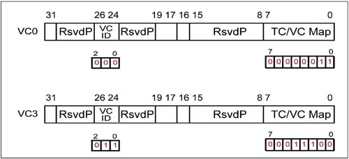
The value "n" represents the number of additional VCs implemented. For example, if the Extended VCs Count contains a value of 3, then n=1, 2, and 3 for the three additional register sets. Note that these numbers simply identify the register sets for each VC supported and is not the VC ID. Software assigns a VC ID for each of the additional VCs being used via the VC ID field within the VCn Resource Control Register. (See Figure 6-5) These IDs are not required to be assigned contiguous values, but the same VC value can be used only once. Assigning TCs to each VC — TC/VC MappingThe Traffic Class value assigned by a requester to each transaction must be associated with a VC as it traverses each link on its journey to the recipient. Also, the VC ID associated with a given TC may change from link to link. Configuration software establishes this association during initialization via the TC/VC Map field of the VC Resource Control Register. This 8-bit field permits any TC value to be mapped to the selected VC, where each bit position represents the corresponding TC value (i.e., bit 0 = TC0:: bit 7 = TC7). Setting a bit assigns the corresponding TC value to the VC ID. Figure 6-6 shows a mapping example where TC0 and TC1 are mapped to VC0 and TC2::TC4 are mapped to VC3. Figure 6-6. TC to VC Mapping Example
Software is permitted a great deal of flexibility in assigning VC IDs and mapping the associated TCs. However, the specification states several rules associated with the TC/VC mapping:
Table 6-1 on page 263 lists a variety of combinations that may be implemented. This is intended only to illustrate a few combinations, and many more are possible.
 |
| [ Team LiB ] |
|