| [ Team LiB ] |


|
ArbitrationTwo types of transaction arbitration provide the method for managing isochronous transactions and differentiated services:
Arbitration is also affected by the requirements associated with transaction ordering and flow control. These additional requirements are discussed in subsequent chapters, but are mentioned in the context of arbitration as required in the following discussions. Virtual Channel ArbitrationIn addition to supporting QoS objectives, VC arbitration should also ensure that forward progress is made for all transactions. This prevents inadvertent split transaction time-outs. Any device that both initiates transactions and supports two or more VCs must implement VC arbitration. Furthermore, other device types that support more than one VC (e.g., switches) must also support VC arbitration. VC arbitration allows a transmitting device to determine the priority of transactions based on their VC assignment. Key characteristics of VCs that are relevant to VC arbitration include:
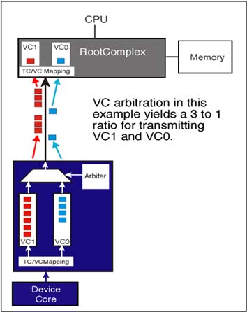
Figure 6-7 on page 265 illustrates the concept of VC arbitration. In this example two VCs are implemented (VC0 and VC1) and transmission priority is based on a 3:1 ratio, where 3 VC1 transactions are sent to each VC0 transaction. The device core issues transactions (that include a TC value) to the TC/VC Mapping logic. Based on the associated VC value, the transaction is routed to the appropriate VC buffer where it awaits transmission. The VC arbiter determines the VC buffer priority when sending transactions. Figure 6-7. Conceptual VC Arbitration Example
This example illustrates the flow of transaction in only one direction. The same logic exists for transmitting transactions simultaneously in the opposite direction. That is, the root port also contains transmit buffers and an arbiter and the endpoint device contains receive buffers. A variety of VC arbitration mechanisms may be employed by a given design. The method chosen by the designer is specified within the VC capability registers. In general, there are three approaches that can be taken:
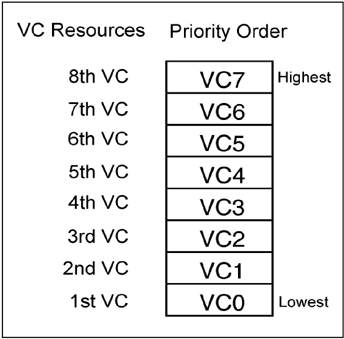
Strict Priority VC ArbitrationThe specification defines a default priority scheme based on the inherent priority of VC IDs (VC0=lowest priority and VC7=highest priority). The arbitration mechanism is hardware based, and requires no configuration. Figure 6-8 illustrates a strict priority arbitration example that includes all VCs. The VC ID governs the order in which transactions are sent. The maximum number of VCs that use strict priority arbitration cannot be greater than the value in the Extended VC Count field. (See Figure 6-4 on page 260.) Furthermore, if the designer has chosen strict priority arbitration for all VCs supported, the Low Priority Extended VC Count field of Port VC Capability Register 1 is hardwired to zero. (See Figure 6-9 on page 267.) Figure 6-8. Strict Arbitration Priority
Figure 6-9. Low Priority Extended VC Count
Strict priority requires that VCs of higher priority get precedence over lower priority VCs based on the VC ID. For example, if all eight VCs are governed by strict priority, transactions with a VC ID of VC0 can only be sent when no transactions are pending transmission in VC1-VC7. In some circumstances strict priority can result in lower priority transactions being starved for bandwidth and experiencing extremely long latencies. Conversely, the highest priority transactions receive very high bandwidth with minimal latencies. The specification requires that high priority traffic be regulated to avoid starvation, and further defines two methods of regulation:
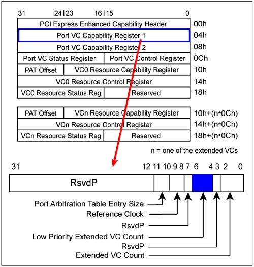
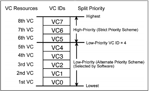
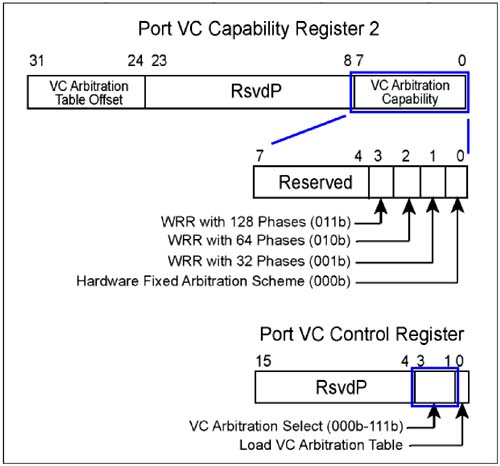
The designer of a device may also limit the number of VCs that participate in strict priority by specifying a split between the low- and high-priority VCs as discussed in the next section. Low- and High-Priority VC ArbitrationFigure 6-9 on page 267 illustrates the Low Priority Extended VC Count field within VC Capability Register 1. This read-only field specifies a VC ID value that identifies the upper limit of the low-priority arbitration group for the design. For example, if this count contains a value of 4, then VC0-VC4 are members of the low-priority group and VC5-VC7 use strict priority. Note that a Low Priority Extended VC Count of 7 means that no strict priority is used. As depicted in Figure 6-11 on page 269, the high-priority VCs continue to use strict priority arbitration, while the low-priority arbitration group uses one of the other prioritization methods supported by the device. VC Capability Register 2 reports which alternate arbitration methods are supported for the low priority group, and the VC Control Register permits selection of the method to be used by this group. See Figure 6-10 on page 268. The low-priority arbitration schemes include:
Figure 6-11. VC Arbitration with Low-and High-Priority Implementations
Figure 6-10. Determining VC Arbitration Capabilities and Selecting the Scheme
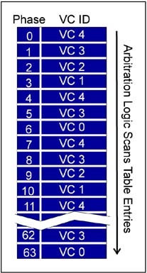
Hardware Fixed Arbitration SchemeThis selection defines a hardware-based VC arbitration scheme that requires no additional software setup. The specification mentions standard Round Robin arbitration as an example scheme that the designer may choose. In such a scheme, transactions pending transmission within each low-priority VC are sent during each pass through the round robin. The specification does not preclude other implementation-specific schemes. Weighted Round Robin Arbitration SchemeThe weighted round robin (WRR) approach permits software to configure the VC Arbitration table. The number of arbitration table entries supported by the design is reported in the VC Arbitration Capability field of Port VC Capability Register 2. The table size is selected by writing the corresponding value in to the VC Arbitration Select field of the Port VC Control Register. See Figure 6-10 on page 268. Each entry in the table represents one phase that software loads with a low priority VC ID value. The VC arbiter repeatedly scans all table entries in a sequential fashion and sends transactions from the VC buffer specified in the table entries. Once a transaction has been sent, the arbiter immediately proceeds to the next phase. Software can set up the VC arbitration table such that some VCs are listed in more entries than others; thereby, allowing differentiation of QoS between the VCs. This gives software considerable flexibility in establishing the desired priority. Figure 6-12 on page 270 depicts the weighted round robin VC arbitration concept. Figure 6-12. Weighted Round Robin Low-Priority VC Arbitration Table Example
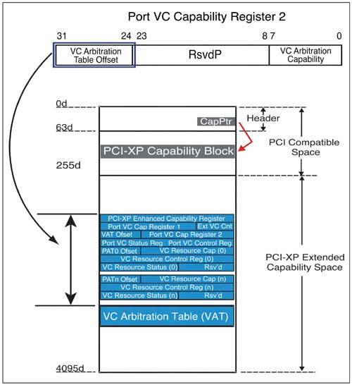
Round Robin Arbitration (Equal or Weighted) for All VCsThe hardware designer may choose to implement one of the round robin forms of VC arbitration for all VCs. This is accomplished by specifying the highest VC number supported by the device as a member of the low priority group (via the Lowest Priority Extended Count field. In this case, all VC priorities are managed via the VC arbitration table. Note that the VC arbitration table is not used when the Hardware Fixed Round Robin scheme is selected. See page 269. Loading the Virtual Channel Arbitration TableThe VC Arbitration Table (VAT) is located at an offset from the beginning of the extended configuration space as indicated by the VC Arbitration Table Offset field. This offset is contained within Port VC Capability Register 2. (See Figure 6-13 on page 271.) Figure 6-13. VC Arbitration Table Offset and Load VC Arbitration Table Fields
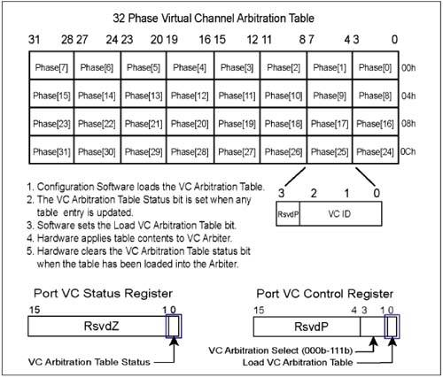
Refer to Figure 6-14 on page 272 during the following discussion. Each entry within the VAT is a 4-bit field that identifies the VC ID of the virtual channel buffer that is scheduled to deliver data during this corresponding phase. The table length is a function of the hardware design and the arbitration scheme selected if choices are supported by the design as illustrated in Figure 6-10 on page 268. Figure 6-14. Loading the VC Arbitration Table Entries
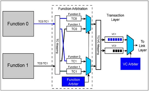
The table is loaded by configuration software to achieve the priority order desired for the virtual channels. Hardware sets the VC Arbitration Table Status bit when software updates any entry within the table. Once the table is loaded, software sets the Load VC Arbitration Table bit within the Port VC Control register. This bit causes hardware to load the new values into the VC Arbiter. Hardware clears the VC Arbitration Table Status bit when table loading is complete; thereby, permitting software to verify successful loading. VC Arbitration within Multiple Function EndpointsThe specification does not state how an endpoint should manage the arbitration of data flows from different functions within an endpoint. However it does state that "Multi-function Endpoints... should support PCI Express VC-based arbitration control mechanisms if multiple VCs are implemented for the PCI Express Link." VC arbitration when there are multiple functions raises interesting questions about the approach to be taken. Of course when the device functions support only VC0, no VC arbitration is necessary. The specification leaves the approach open to the designer. Figure 6-15 on page 274 shows a functional block diagram of an example implementation in which two functions are implemented within an endpoint device, each of which supports two VCs. The example approach is based upon the goal of using a standard PCI Express core to interface both functions to the link. The transaction layer within the link performs the TC/VC mapping and VC arbitration. The device-specific portion of the design is the function arbiter that determines the priority of data flows from the functions to the transaction layer of the core. Following are key considerations for such an approach:
Figure 6-15. Example Multi-Function Endpoint Implementation with VC Arbitration
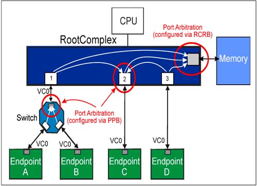
Port ArbitrationWhen traffic from multiple ports vie for limited bandwidth associated with a common egress port, arbitration is required. The concept of port arbitration is pictured in Figure 6-16 on page 275. Note that port arbitration exists in three locations within a system:
Figure 6-16. Port Arbitration Concept
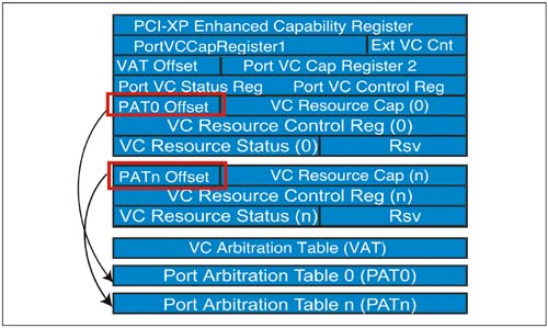
Port arbitration requires software configuration, which is handled via PCI-to-PCI bridge (PPB) configuration in both switches and peer-to-peer transfers within the Root Complex and by the Root Complex Register Block when accessing shared root complex resources such as main memory. Port arbitration occurs independently for each virtual channel supported by the egress port. In the example below, root port 2 supports peer-to-peer transfers from root ports 1 and 2; however, peer-to-peer transfer support between root complex ports is not required. Because port arbitration is managed independently for each VC of the egress port or RCRB, a port arbitration table is required for each VC that supports programmable port arbitration as illustrated in Figure 6-17 on page 276. Port arbitration tables are supported only by switches and RCRBs and are not allowed for endpoints, root ports and PCI Express bridges. Figure 6-17. Port Arbitration Tables Needed for nEach VC
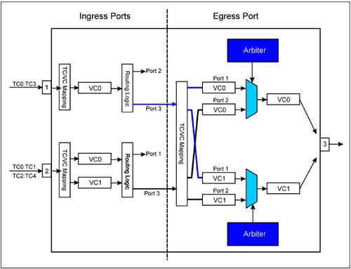
The process of arbitrating between different packet streams also implies the use of additional buffers to accumulate traffic from each port in the egress port as illustrated in Figure 6-18 on page 277. This example illustrates two ingress ports (1 and 2) whose transactions are routed to an egress port (3). The action taken by the switch include:
Figure 6-18. Port Arbitration Buffering
The Port Arbitration MechanismsThe actual port arbitration mechanisms defined by the specification are similar to the models used for VC arbitration and include:
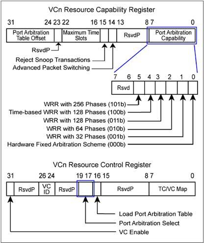
Configuration software must determine the port arbitration capability for a switch or RCRB and select the port arbitration scheme to be used for each enabled VC. Figure 6-19 on page 278 illustrates the registers and fields involved in determining port arbitration capabilities and selecting the port arbitration scheme to be used by each VC. Figure 6-19. Software checks Port Arbitration Capabilities and Selects the Scheme to be Used
Non-Configurable Hardware-Fixed ArbitrationThis port arbitration mechanism does not require configuration of the port arbitration table. Once selected by software, the mechanism is managed solely by hardware. The actual arbitration scheme is based on a round-robin or similar approach where each port has the same priority. This type of mechanism ensures a type of fairness and ensures that all transactions can make forward progress. However, it does not service the goals of differentiated services and does not support isochronous transactions. Weighted Round Robin ArbitrationLike the weighted round robin mechanism used for VC arbitration, software loads the port arbitration table such that some ports can receive higher priority than others based on the number of phases in the round robin that are allocated for each port. This approach allows software to facilitate differentiated services by assigning different weights to traffic coming from different ports. As the table is scanned each table phase specifies a port number that identifies the VC buffer from which the next transaction is sent. Once the transaction is delivered arbitration control logic immediately proceeds to the next phase. For a given port, if no transaction is pending transmission the arbiter advances immediately to the next phase. The specification defines four table lengths for WRR port arbitration, determined by the number of phases used by the table. The table length selections include:
Time-Based, Weighted Round Robin ArbitrationThe time-based WRR mechanism is required for supporting isochronous transactions. Consequently, each switch egress port and RCRB that supports isochronous transactions must implement time-based WRR port arbitration. Time-based weighted round robin adds the element of a virtual timeslot for each arbitration phase. Just as in WRR the port arbiter delivers one transaction from the Ingress Port VC buffer indicated by the Port Number of the current phase. However, rather than immediately advancing to the next phase, the time-based arbiter waits until the current virtual timeslot elaspses before advancing. This ensures that transactions are accepted from the ingress port buffer at regular intervals. Note that the timeslot does not govern the duration of the transfer, but rather the interval between transfers. The maximum duration of a transaction is the time it takes to complete the round robin and return to the original timeslot. Each timeslot is defined as 100ns. Also, it is possible that no transaction is delivered during a timeslot, resulting in an idle timeslot. This occurs when:
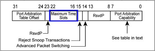
Time-based WRR arbitration supports a maximum table length of 128 phases. The actual number of phases implemented is reported via the Maximum Time Slot field of each virtual channel that supports Timed WRR arbitration. See the Figure 6-20 on page 280 which illustrate the Maximum Time Slots Field within the VCn Resource Capability register. See MindShare's website for a white paper on example applications of Time-Based WRR. Figure 6-20. Maximum Time Slots Register
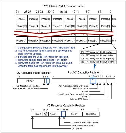
Loading the Port Arbitration TablesA port arbitration table is required for each VC supported by the egress port. The actual size and format of the Port Arbitration Tables are a function of the number of phases and the number of ingress ports supported by the Switch, RCRB, or Root Port that supports peer-to-peer transfers. The maximum number of ingress ports supported by the Port Arbitration Table is 256 ports. The actual number of bits within each table entry is design dependent and governed by the number of ingress ports whose transactions can be delivered to the egress port. The size of each table entry is reported in the 2-bit Port Arbitration Table Entry Size field of Port VC Capability Register 1. The permissible values are:
Configuration software loads each table with port numbers to accomplish the desired port priority for each VC supported. As illustrated in Figure 6-21 on page 281, the port arbitration table format depends on the size of each entry and the number of time slots supported by this design. Figure 6-21. Format of Port Arbitration Table
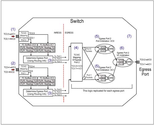
Switch Arbitration ExampleThis section provides an example of a three-port switch with both Port and VC arbitration illustrated. The example presumes that packets arriving on ingress ports 0 and 1 are moving in the upstream direction and port 2 is the egress port facing the Root Complex. This example serves to summarize port and VC arbitration and illustrate their use within a PCI Express switch. Refer to Figure 6-22 on page 283 during the following discussion.
Figure 6-22. Example of Port and VC Arbitration within A Switch
 |
| [ Team LiB ] |
|