| [ Team LiB ] |


|
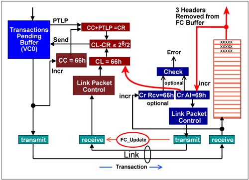
Flow Control Updates Following FC_INITThe receiver must continually update its neighboring device to report additional Flow Control credits that have accumulated as a result of moving transactions from the Flow Control buffer. Figure 7-13 on page 309 illustrates an example where the transmitter was previously blocked from sending header transactions because the Flow Control buffer was full. In the example, the receiver has just removed three headers from the Flow Control buffer. More space is now available, but the neighboring device has no knowledge of this. As each header is removed from the Flow Control buffer, the CREDITS_ALLOCATED count increments. The new count is delivered to the CREDIT_LIMIT register of the neighboring device via an update Flow Control packet. The updated credit limit allows transmission of additional transactions. Figure 7-13. Flow Control Update Example
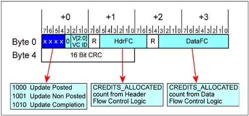
FC_Update DLLP Format and ContentRecall that update Flow Control packets, like the Flow Control initialization packets contain two update fields, one for header and one for data for the selected credit type (P, NP, and Cpl). Figure 7-14 on page 310 depicts the content of the update packet. The receiver's CREDITS_ALLOCATED counts that are reported in the HdrFC and DataFC fields may have been updated many times or not at all since the last update packet sent. Figure 7-14. Update Flow Control Packet Format and Contents
Flow Control Update FrequencyThe specification defines a variety of rules and suggested implementations that govern when and how often Flow Control Update DLLPs should be sent. The motivation includes:
The update frequency limits specified assume that the link is in the active state (L0 or LOs (s=standby). All other link states represent more aggressive power management with longer recovery latencies that require link recovery prior to sending packets. Immediate Notification of Credits AllocatedWhen a Flow Control buffer has filled to the extent that maximum-sized packets cannot be sent, the specification requires immediate delivery of an FC_Update DLLP when the deficit is eliminated. Specifically, when additional credits are allocated by a receiver that guarantee sufficient space now exists to accepts another maximum-sized packet, an Update packet must be sent. Two cases exist:
Maximum Latency Between Update Flow Control DLLPsThe transmission frequency of Update FCPs for each FC credit type (non-infinite) must be scheduled for transmission at least once every 30 µs (-0%/+50%). If the Extended Sync bit within the Control Link register is set, Updates must be scheduled no later than every 120 µs (-0%/+50%). Note that Update FCPs may be scheduled for transmission more frequently than is required. Calculating Update Frequency Based on Payload Size and Link WidthThe specification offers a formula for calculating the frequency at which update packets need to be sent for maximum data payloads sizes and link widths. The formula, shown below, defines FC Update delivery intervals in symbol times (.4ns).
where:
The simple relationship defined by the formula show that for a given data payload and buffer size, the frequency of update packet delivery becomes higher as the link width increases. This relatively simple approach suggests a timer implementation that triggers scheduling of update packets. Note that this formula does not account for delays associated with the receiver or transmitter being in the L0s power management state. The specification recognizes that the formula will be inadequate for many applications such as those that stream large blocks of data. These applications may require buffer sizes larger than the minimum specified, as well as a more sophisticated update policy in order to optimize performance and reduce power consumption. Because a given solution is dependent on the particular requirements of an application, no definition for such policies is provided. Error Detection Timer — A Pseudo RequirementThe specification defines an optional time-out mechanism that is highly recommended. So much so, that the specification points out that it is expected to become a requirement in futures versions of the spec. This mechanism detects prolonged absences of Flow Control packets. The maximum latency between FC packets for a given Flow Control credit type is specified to be no greater than 120µs. This error detection timer has a maximum limit of 200µs, and it gets reset any time a Flow Control packet of any type is received. If a time-out occurs, this suggests a serious problem with a device's ability to report Flow Control credits. Consequently, a time-out triggers the Physical Layer to enter its Recovery state which retrains the link and hopefully clears the error condition. Characteristics of this timer include:
|

| [ Team LiB ] |
|