[ Team LiB ] Previous Section Next Section

Flow Control Initialization

Prior to sending any transactions, flow control initialization must be performed. Initialization occurs for each link in the system and involves a handshake between the devices attached to the same link. TLPs associated with the virtual channel being initialized cannot be forwarded across the link until Flow Control Initialization is performed successfully.

Once initiated, the flow control initialization procedure is fundamentally the same for all Virtual Channels. The small differences that exist are discussed later. Initialization of VC0 (default VC) must be done in hardware so that configuration transactions can traverse the PCI Express fabric. Other VCs initialize once configuration software has set up and enabled the VCs at both ends of the link. Enabling a VC triggers hardware to perform flow control initialization for this VC.

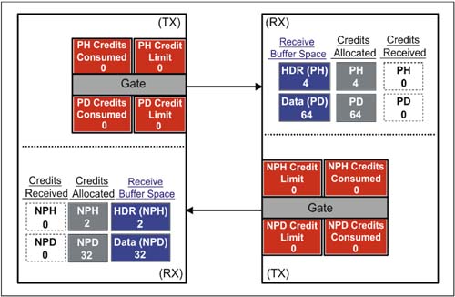
Figure 7-9 pictures the Flow Control counters within the devices at both ends of the link, along with the state of flag bits used during initialization.

Figure 7-9. Initial State of Example FC Elements

graphics/07fig09.jpg

The FC Initialization Sequence

PCI Express defines two stages in flow control initialization: FC_INIT1 and FC_INIT2. Each stage of course involves the use of the Flow Control packets (FCPs).

  • Flow Control Init1 — reports the size of the Flow Control buffers for a given virtual channel

  • Flow Control Init2 — verifies that the device transmitting the Init2 packet has completed the flow control initialization for the specified VC and buffer type.

FC Init1 Packets Advertise Flow Control Credits Available

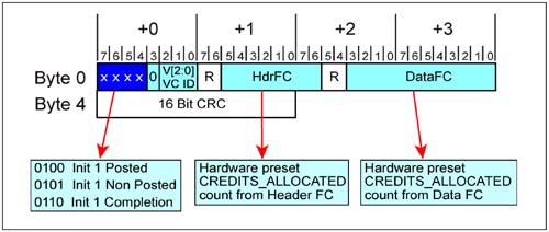
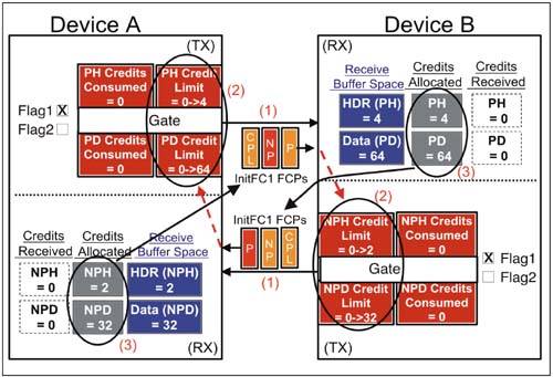
During the FC_INIT1 state, a device continuously outputs a sequence of 3 InitFC1 Flow Control packets advertising its posted, non-posted, and completion receiver buffer sizes. (See Figure 7-10.) Each device also waits to receive a similar sequence from its neighbor. Once a device has received the complete sequence and sent its own, it initializes transmit counters, sets an internal flag FI1, and exits FC_INIT1. This process is illustrated in Figure 7-11 on page 306 and described below. The example shows Device A reporting Non-Posted Buffer Credits and Device B reporting Posted Buffer Credits. This illustrates that the devices need not be in synchronization regarding what they are reporting. In fact, the two device will typically not start the flow control initialization process at the same time.

  1. Each device sends InitFC1 type Flow Control packets (FCPs) to advertise the size of its respective receive buffers. A separate FCP for posted requests (P), non-posted requests (NP) and completion (CPL) packet types is required. The order in which this sequence of three FCPs is sent is:

    • Header and Data buffer credit units for Posted Requests (P).

    • Header and Data buffer credit units for Non-Posted Requests (NP)

    • Header and Data buffer credit units for Completions (CPL)

    The sequence of FCPs is repeated continuously until a device leaves the FC_INIT1 initialization state.

  2. In the meantime, devices take the credit information and initialize the transmit credit limit registers. In this example, Device A loads its PH transmit Credit Limit register with a value of 4, which was reported by Device B for its posted request header FC buffer. It also loads its PD Credit Limit register with a value of 64d credits (1024 bytes worth of data) for accompanying posted data. Similarly, Device B loads its NPH transmit Credit Limit counter with a value of 2 for non-posted request headers and its NPD transmit counter with a value of 32d credits (512 bytes worth of data) for accompanying non-posted data.

  3. Note that when this process is complete, the Credits Allocated counter in the receivers and the corresponding Credit Limit counters in the transmitters will be equal.

  4. Once a device receives Init1 FC values for a given buffer type (e.g., Posted) and has recorded them, the FC_INIT1 state is complete for that Flow Control buffer. Once all FC buffers for a given VC have completed the FC_INIT1 state, Flag 1 (Fl1) is set and the device ceases to send FCInit1 DLLPs and advances to FC Init2 state. Note that receipt of an Init2 FC packets may also cause Fl1 to be set. This can occur if the neighboring device has already advanced to the FC Init2 state.

Figure 7-10. INIT1 Flow Control Packet Format and Contents

graphics/07fig10.jpg

Figure 7-11. Devices Send and Initialize Flow Control Registers

graphics/07fig11.jpg

FC Init2 Packets Confirm Successful FC Initialization

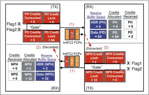
PCI Express defines the InitFC2 state that is used for feedback to verify the Flow Control initialization has been successful for a given VC. During FC_INIT2, each device continuously outputs a sequence of 3 InitFC2 Flow Control packets; however, credit values are discarded during the FC_INIT2 state. Note that devices are permitted to send TLPs upon entering the FC_INIT2 state. Figure 7-12 illustrates InitFC2 behavior, which is described following the illustration.

  1. At the start of initialization state FC_INIT2, each device commences sending InitFC2 type Flow Control packets (FCPs) to indicate it has completed the FC_INIT1 state. Devices use the same repetitive sequence when sending FCPs in this state as before:

    • Header and Data buffer credit allocation for Posted Requests (P)

    • Header and Data buffer credit allocation for Non-Posted Requests (NP)

    • Header and Data buffer credit allocation for Completions (CPL)

  2. All credits reported in InitFC2 FCPs may be discarded, as the transmitter Credit Limit counters were already set up in FC_INIT1.

  3. Once a device receives an FC_INIT2 packet for any buffer type, it sets an internal flag (Fl2). (It doesn't wait to receive an FC_Init2 for each type.) Note that Fl2 is also set upon receipt of an UpdateFC packet or TLP.

Figure 7-12. Device Confirm that Flow Control Initialization is Completed for a Given Buffer

graphics/07fig12.jpg

Rate of FC_INIT1 and FC_INIT2 Transmission

The specification defines the latency between sending FC_INIT DLLPs as follows:

  • VC0. Hardware initiated flow control of VC0 requires that FC_INIT1 and FC_INIT2 packets be transmitted "continuously at the maximum rate possible." That is, the resend timer is set to a value of zero.

  • VC1-VC7. When software initiates flow control initialization, the FC_INIT sequence is repeated "when no other TLPs or DLLPs are available for transmission." However, the latency between the beginning of one sequence to the next can be no greater than 17µs.

Violations of the Flow Control Initialization Protocol

A violation of the flow control initialization protocol can be optionally checked by a device. An error detected can be reported as a Data Link Layer protocol error. See "Link Flow Control-Related Errors" on page 363.

    [ Team LiB ] Previous Section Next Section