| [ Team LiB ] |


|
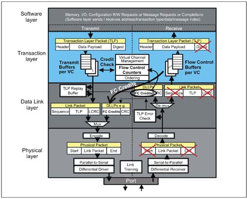
Flow Control ConceptThe ports at each end of every PCI Express link must implement Flow Control. Before a transaction packet can be sent across a link to the receiving port, the transmitting port must verify that the receiving port has sufficient buffer space to accept the transaction to be sent. In many other architectures including PCI and PCI-X, transactions are delivered to a target device without knowing if it can accept the transaction. If the transaction is rejected due to insufficient buffer space, the transaction is resent (retried) until the transaction completes. This procedure can severely reduce the efficiency of a bus, by wasting bus bandwidth when other transactions are ready to be sent. Because PCI Express is a point-to-point implementation, the Flow Control mechanism would be ineffective, if only one transaction stream was pending transmission across a link. That is, if the receive buffer was temporarily full, the transmitter would be prevented from sending a subsequent transaction due to transaction ordering requirements, thereby blocking any further transfers. PCI Express improves link efficiency by implementing multiple flow-control buffers for separate transaction streams (virtual channels). Because Flow Control is managed separately for each virtual channel implemented for a given link, if the Flow Control buffer for one VC is full, the transmitter can advance to another VC buffer and send transactions associated with it. The link Flow Control mechanism uses a credit-based mechanism that allows the transmitting port to check buffer space availability at the receiving port. During initialization each receiver reports the size of its receive buffers (in Flow Control credits) to the port at the opposite end of the link. The receiving port continues to update the transmitting port regularly by transmitting the number of credits that have been freed up. This is accomplished via Flow Control DLLPs. Flow control logic is located in the transaction layer of the transmitting and receiving devices. Both transmitter and receiver sides of each device are involved in flow control. Refer to Figure 7-1 on page 287 during the following descriptions.
Figure 7-1. Location of Flow Control Logic
 |
| [ Team LiB ] |
|