| [ Team LiB ] |


|
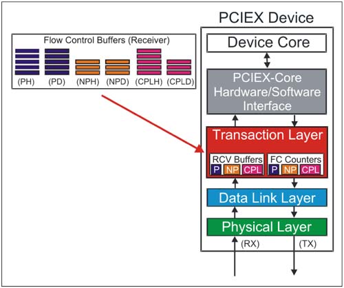
Flow Control BuffersFlow control buffers are implemented for each VC resource supported by a PCI Express port. Recall that devices at each end of the link may not support the same number of VC resources, therefore the maximum number of VCs configured and enabled by software is the greatest number of VCs in common between the two ports. VC Flow Control Buffer OrganizationEach VC Flow Control buffer at the receiver is managed for each category of transaction flowing through the virtual channel. These categories are:
In addition, each of these categories is separated into header and data portions of each transaction. Flow control operates independently for each of the six buffers listed below (also see Figure 7-2 on page 289).
Figure 7-2. Flow Control Buffer Organization
Some transactions consist of a header only (e.g., read requests) while others consist of a header and data (e.g., write requests). The transmitter must ensure that both header and data buffer space is available as required for each transaction before the transaction can be sent. Note that when a transaction is received into a VC Flow Control buffer that ordering must be maintained when the transactions are forwarded to software or to an egress port in the case of a switch. The the receiver must also track the order of header and data components within the Flow Control buffer. Flow Control CreditsBuffer space is reported by the receiver in units called Flow Control credits. The unit value of Flow Control credits (FCCs) may differ between header and data as listed below:
Flow control credits are passed within the header of the link layer Flow Control Packets. Note that DLLPs do not require Flow Control credits because they originate and terminate at the link layer. Maximum Flow Control Buffer SizeThe maximum buffer size that can be reported via the Flow Control Initialization and Update packets for the header and data portions of a transaction are as follows: 128 Credits for headers
2048 Credits for data
The reason for these limits is discussed in the section entitled "Stage 1 — Flow Control Following Initialization" page 296, step 2.  |
| [ Team LiB ] |
|