| [ Team LiB ] |


|
Legacy PCI Interrupt DeliveryThis section provides background information regarding the standard PCI interrupt delivery using INTx signals. This is followed by a detailed discussion of how PCI Express supports virtual INTx signaling. Readers familiar with PCI interrupt handling may wish to proceed to "Virtual INTx Signaling" on page 347. Background — PCI Interrupt SignalingPCI devices that use interrupts have two options:
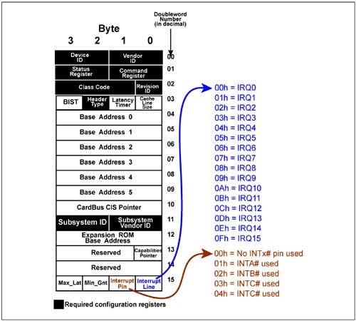
Device INTx# PinsEach physical PCI component can implement up to 4 INTx# signals (INTA#, INTB#, INTC#, and INTD#). Because PCI devices (like PCI Express devices) can support up to 8 functions, four interrupt pins are supported. However, if a maximum of eight functions are implemented and all required interrupts then the INTx# signals would have to be shared. Also, no single function is permitted to use more than one INTx# signal. Determining if a Function Uses INTx# PinsEach PCI function indicates support for an INTx# signal via the standard configuration header. The read-only Interrupt Pin register illustrated in Figure 9-7 on page 343, contains the information needed by configuration software to determine if INTx signals are supported and, if so, which INTx# signal is used by this function. Figure 9-7. Interrupt Pin Register within PCI Configuration Header
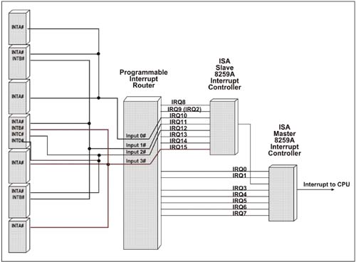
Interrupt RoutingThe system designer determines the routing of INTx pins from devices. The INTx signals used by each device can be routed in a variety of ways so that ultimately the each INTx pin will go to an input of the interrupt controller. Figure 9-8 on page 344 illustrates a variety of PCI devices using INTx pins to signal interrupts. As is typical, all PCI INTx signals are routed to one of four inputs. All INTx signals routed to a given input will be directed to a specific input to the interrupt controller, thus each of the INTx routed to the common interrupt input will also have the same interrupt Line number assigned to it by platform software. For example, IRQ15 has three PCI INTx inputs from different devices — INTB#, INTA#, and INTA#. Consequently, the functions using these INTx lines will share IRQ15 and its associated interrupt vector. Figure 9-8. INTx Signal Routing is Platform Specific
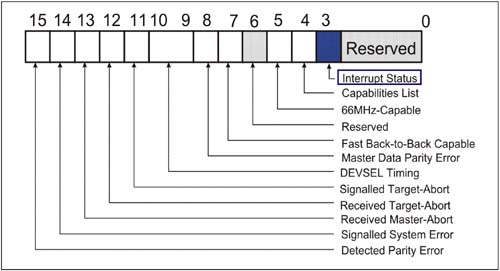
Associating the INTx# Line to an IRQ NumberBased on the routing of the INTx pin associated with each function, the Interrupt Line number is reported by configuration software (also pictured in Figure 9-7 on page 343). The value ultimately tells the function's device driver which interrupt vector will be reported when an interrupt occurs from this function. Therefore, when this function generates an interrupt the CPU will receive the vector number that corresponds to the IRQ specified in the Interrupt Line register. The CPU uses this vector to index into the interrupt service table to fetch the entry point of the interrupt service routine associated with the function's device driver. The method used to communicate this information is operating environment specific (e.g., the Windows XP or Linux). Note that because the INTx# lines can be wire ORed from different devices, the interrupt line number assignment will be the same for those devices whose INTx# lines are wired together. In these cases, an interrupt signaled by any of the devices sharing the same IRQ will cause the same vector to be sent to the CPU. Software must ensure that all service routines that share the same IRQ input chain the service routines together so that all devices can be checked to determine which one(s) caused the interrupt request. Once again the mechanism used for chaining the service routines is operating environment specific. INTx# SignalingThe INTx# lines are active low signals implemented as open-drain with a pullup resistor provided on each line by the system. Multiple devices connected to the same PCI interrupt request signal line can assert it simultaneously without damage. When a device signals an interrupt it also sets a bit within a device-specific register to indicate that an interrupt is pending. This register can be mapped into memory or I/O address space and is read by device-specific software to verify that an interrupt is pending completion. When this bit is cleared, the INTx signal is deasserted. The device must also set the Interrupt Status bit located in the Configuration Status register. This bit can be read by system software to see if an interrupt is currently pending completion. (See Figure 9-10 on page 347.) Figure 9-10. Configuration Status Register — Interrupt Status Field
Interrupt DisableThe 2.3 specification added an interrupt disable bit (Bit 10) to the configuration command register. See Figure 9-9 on page 346. The bit is cleared at reset permitting generation of INTx signal generation. Software may set this bit thereby inhibiting generation of INTx signaling. Note that the Interrupt Disable bit has no effect on Message Signalled Interrupts (MSI). MSIs are enabled via the MSI capability command register. Figure 9-9. Configuration Command Register — Interrupt Disable Field
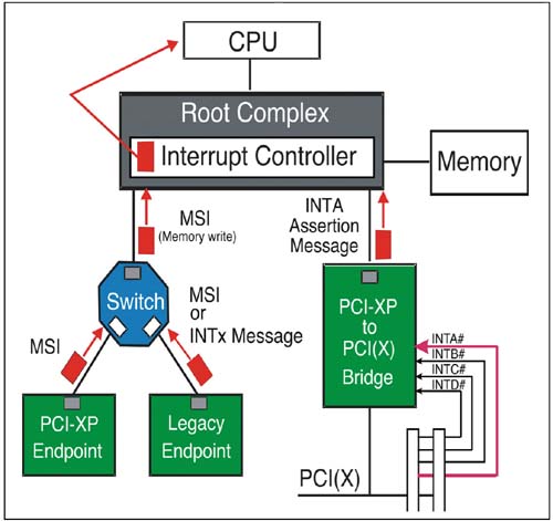
Interrupt StatusThe PCI 2.3 specification added an interrupt status bit to the configuration status register (pictured in Figure 9-10 on page 347). A function must set this status bit when an interrupt is pending. In addition, if the Interrupt Disable bit in the configuration command register is cleared (i.e. interrupts enabled), then the function's INTx# signal is asserted, but only after the interrupt status bit is set. This bit is unaffected by the state of the interrupt disable bit, and it has no effect on the MSI mechanism. Note also that the bit is read only. Virtual INTx SignalingWhen circumstances make it impossible to use MSIs standard compatible INTx signaling may be used. Following are two examples of devices that cannot use MSI: PCI Express-to-PCI(X) bridges — PCI devices will likely use the INTx signals to deliver an interrupt request (MSI is optional). Because PCI Express does not support sideband interrupt signaling, an INTx virtual wire message is used to signal the interrupt controller (located in the Root Complex). The interrupt controller in turn delivers an interrupt request to the CPU, including the vector number that identifies the entry point of the interrupt service routine. Boot Devices — Standard PC systems typically use the legacy interrupt subsystem (8259 interrupt controller and related signals) during the boot sequence. Furthermore, the MSI subsystem cannot be used because it typically initializes after the Operating System (OS) loads and device drivers initialize. PCI Express devices involved in initializing the system and loading the OS (e.g., video, hard drive, and keyboard) are called "boot devices." Boot devices must use legacy interrupt support until the OS and device drivers for their devices install, after which they use MSI. Virtual INTx Wire DeliveryFigure 9-11 on page 348 illustrates an example PCI Express system that implements a legacy boot device and a PCI Express-to-PCI Bridge. The bridge can never issue MSIs because it does not know the source of the INTx# signals; whereas, the boot device can signal interrupt via MSI following the boot sequence. Figure 9-11 depicts the bridge using an INTB messages to signal the assertion and deassertion of INTB# from the PCI bus. The legacy device is shown signaling an INTA from its function. Note that INTx signaling involves two messages:
Figure 9-11. Legacy Devices Use INTx Messages Virtualize INTA#-INTD# Signal Transitions
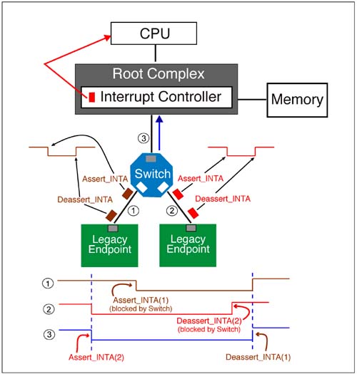
When a Legacy device delivers an Assert_INTx message, it also sets its Interrupt Pending bit located in memory or I/O space and also sets the Interrupt Pending bit located within the Configuration Status register (Figure 9-10). Collapsing INTx Signals within a BridgeSwitches that have multiple downstream ports to which legacy devices attach must ensure that INTx transactions are delivered upstream in the correct fashion. The specific requirement is to ensure that the interrupt controller receives INTx messages that represent the wire-ORed behavior of legacy PCI implementations. As illustrated in Figure 9-8 on page 344, INTx lines may be shared when one or more INTx lines are tied together (wire-ORed). Consequently, when more than one devices signals an interrupt at roughly the same time only the first assertion is seen by the interrupt controller. Similarly, when one of these devices deasserts its INTx line, the line remains asserted and only the last deassertion will be seen by the interrupt controller. Two or more legacy PCI Express devices sending the same INTx message on different ports of the same switch, must be treated as wire-ORed messages. This ensures that the interrupt controller observes the correct transitions. Figure 9-12 on page 350 illustrates two legacy devices issuing INTA messages to the Switch. Note that because the INTA messages overlap, the second Assert_INTA is blocked because an Assert_INTA message has been registered and no deassertion has yet occurred. Similarly the first Deassert_INTA message is blocked because two Assert_INTAs are outstanding and this is the first deassert message, so another will follow. This ensures that the interrupt controller will never receive two Assert_INTx messages of the same type nor two Deassert_INTX messages of the same type. Figure 9-12. Switch Collapses INTx Message to Achieve Wired-OR Characteristics
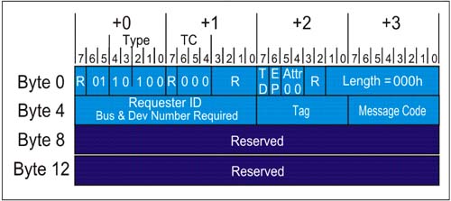
As described above, switches must track the state of each of the INTx messages at each port and transfer only those that represent a valid change in the virtual signaling. INTx Message FormatFigure 9-13 on page 351 depicts the format of the INTx message header and defines the message types supported. INTx messages are always delivered from upstream ports of Endpoints, Bridges, and Switches. The routing employed is "Local-Terminate at Receiver," with the interrupt controller as the ultimate destination. The message code field identifies the message type and eight codes are used by the INTx messages as listed in Table 9-2. Figure 9-13. INTx Message Format and Types
The rules associated with the delivery of INTx messages are consistent with other message types, but have some unique characteristics. The INTx message rules are summarized below:
|

| [ Team LiB ] |
|