| [ Team LiB ] |


|
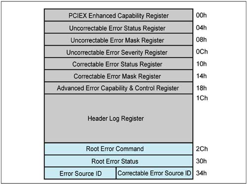
Advanced Error Reporting MechanismsAdvanced Error Reporting requires implementation of the Advanced Error Reporting registers illustrated in Figure 10-14 on page 382. (Note that the lighter fields at the bottom of the Capability register diagram are used only for root ports, discussed later.) These registers provide several additional error reporting features:
Figure 10-14. Advanced Error Capability Registers
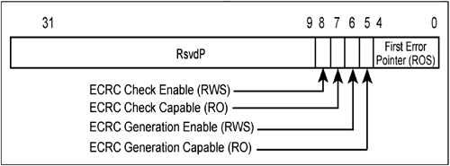
ECRC Generation and CheckingEnd-to-End CRC (ECRC) generation and checking can be enabled only if the Advanced Error Reporting Capability registers are implemented. Specifically, the Advanced Error Capability and Control register provides control over ECRC generation and checking as illustrated in Figure 10-15 on page 383. Figure 10-15. The Advanced Error Capability & Control Register
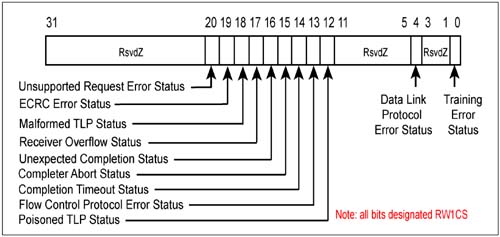
This register reports whether this device supports ECRC generation and checking. If so, configuration software can enable one or both features. In some cases, multiple uncorrectable errors may be detected prior to software reading and clearing the register. The First Error Pointer field identifies the bit position within the Advanced Uncorrectable Status register corresponding to the error that occurred first. (See Figure 10-18 on page 387.) Figure 10-18. Advanced Uncorrectable Error Status Register
The First Error Pointer and the ECRC Check and Generation Enable bits must be implemented as sticky bits. Handling Sticky BitsSeveral of the Advanced Configuration Error Registers employ sticky fields. Many of these fields are single bits. The designations of sticky fields are as follows:
Sticky error register fields behave differently in that a Hot Reset has no affect on the contents of these fields. For all other register fields, Hot Reset forces default values into the fields. Sticky bits are important in error handling to ensure that Error-related control and status information is not lost due to a Hot Reset. Software may initiate a Hot Reset in an attempt to clear errors. Advanced Correctable Error HandlingAdvanced error reporting provides the ability to pinpoint specific correctable errors. These errors can selectively cause the generation of a Correctable Error Message being sent to the host system:
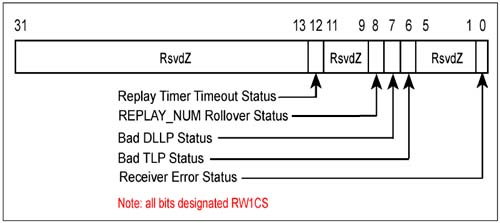
Knowledge of which error has occurred can help system software to make better predictions of components that are likely to fail completely in the future. Software may also choose to mask recognition of some correctable errors while reporting others. Advanced Correctable Error StatusWhen a correctable error occurs the corresponding bit within the Advanced Correctable Error Status register is set. (See Figure 10-16.) These bits are automatically set by hardware and are cleared by software when writing a "1" to the bit position. These bits are set whether or not the error is reported via an Error Message. Each status bit in this register is designated RW1CS. Figure 10-16. Advanced Correctable Error Status Register
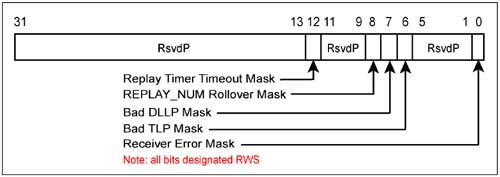
Advanced Correctable Error ReportingWhether a particular correctable error is reported to the host is specified by the Correctable Mask register illustrated in Figure 10-17. The default state of the mask bits are cleared (0), thereby causing a Correctable Error message to be delivered when any of the correctable errors are detected. Software may choose to set one or more bits to prevent a Correctable Error Message from being sent when the selected error is detected. Each bit in this register is designated RWS. Figure 10-17. Advanced Correctable Error Mask Register
Advanced Uncorrectable Error HandlingAdvanced error reporting provides the ability to pinpoint which uncorrectable error has occurred. Furthermore software can specify the severity of each error and select which errors will result in an Error Message being sent to the host system (Root Complex).
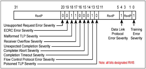
The errors noted as optional in the list above may not be implemented in the Advanced Uncorrectable register set. Advanced Uncorrectable Error StatusWhen an uncorrectable error occurs the corresponding bit within the Advanced Uncorrectable Error Status register is set. (See Figure 10-18 on page 387.) These bits are automatically set by hardware and are cleared by software when writing a "1" to the bit position. These bits are set whether or not the error is reported via an Error Message. Each status bit in this register is designated RW1CS. Selecting the Severity of Each Uncorrectable ErrorAdvanced error handling permits software to select the severity of each error within the Advanced Uncorrectable Error Severity register. This gives software the opportunity to treat errors according to the severity associated with a given application. For example, Poisoned TLP data associated with audio data being sent to a speaker, while not correctable has no serious side effects relative to the integrity of the system. However, if real-time status information is being retrieved that will help make critical decisions, any errors in this data can be very serious. Figure 10-19 illustrates the Error Severity register. The default values are illustrated in the individual bit fields. These represent the default severity levels for each type of error (1 = Fatal, 0 = Non-Fatal). Figure 10-19. Advanced Uncorrectable Error Severity Register
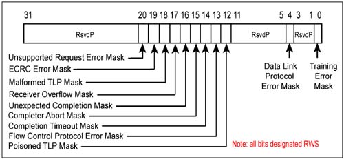
Those uncorrectable errors that are selected to be non fatal will result in a NonFatal Error Message being delivered and those selected as Fatal errors will result in a Fatal Error Message delivered. However, whether or not an Error Message is generated for a given error is specified in the Advanced Uncorrectable Mask register. Uncorrectable Error ReportingSoftware can mask out specific errors so that they never cause an Error Message to be generated. The default condition is to generate Error Messages for each type of error (all bits are cleared). Figure 10-20 on page 389 depicts the Advanced Uncorrectable Error Mask register. Figure 10-20. Advanced Uncorrectable Error Mask Register
Error LoggingA four DWord portion of the Advanced Error Registers block is reserved for storing the header of the transaction that has incurred a failure. Only a select group of Transaction Layer errors result in the transaction header being logged. Table 10-6 lists the transactions that are logged.
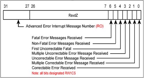
The format of the header is preserved when captured and placed into the register. That is, the illustration of header format in this book is exactly how the headers will appear within the Error Logging register. Note also that the contents of this register are designated ROS. Root Complex Error Tracking and ReportingThe Root Complex is the target of all Error Messages issued by devices within the PCI Express fabric. Errors received by the Root Complex result in status registers being updated and the error being conditionally reported to the appropriate software handler or handlers. Root Complex Error Status RegistersWhen the Root Complex receives an Error Message, it sets status bits within the Root Error Status register (Figure 10-21 on page 391). This register indicates the types of errors received and also indicates when multiple errors of the same type have been received. Note that an error detected at the root port is treated as if the port sent itself an Error Message. Figure 10-21. Root Error Status Register
The Advanced Root Error Status register tracks the occurrence of errors as follows: Correctable Errors
Uncorrectable Errors
Detecting and Reporting First Uncorrectable Fatal versus Non-Fatal ErrorsIf the system wishes to implement separate software error handlers for Correctable, Non-Fatal, and Fatal errors. The Root Error Status register includes bits to differentiate Correctable from Uncorrectable Errors but needs additional bits to also determine whether Uncorrectable errors are fatal or non-fatal:
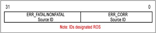
Advanced Source ID RegisterSoftware error handlers may need to read and clear error status registers within the device that detected and reported the error. The Error Messages contain the ID of the device reporting the error. The Source ID register captures the Error Message ID associated with the first Fatal and first Non-Fatal Error message received by the Root Complex. The format of this register is shown in Figure 10-22 on page 391. Figure 10-22. Advanced Source ID Register
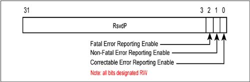
Root Error Command RegisterThe Root Error Status register sets status bits that determines whether a Correctable, Fatal, or Non-Fatal error has occurred. In conjunction with these status bits the Root Complex can also generate separate interrupts that call handlers for each of the error categories. The Root Error Command register enables interrupt generation for all three categories as pictured in Figure 10-23 on page 392. Figure 10-23. Advanced Root Error Command Register
Reporting Errors to the Host SystemSoftware error handlers will initially read Root Complex status registers to determine the nature of the error, and may also need to read device-specific error registers of the device that reported the error.  |
| [ Team LiB ] |
|