| [ Team LiB ] |


|
Baseline Error Detection and HandlingThis section defines the required support for detecting and reporting PCI Express errors. Each PCI Express compliant devices must include:
PCI-Compatible Error Reporting MechanismsEach PCI Express must map required PCI Express error support to the PCI-related error registers. This involves enabling error reporting and setting status bits that can be read by PCI-compliant software. To understand the features available from the PCI-compatible point of view consider the error-related bits of the Command and Status registers located within the Configuration header. While the command and status register bits have the PCI name, some of the field definitions have been modified to reflect the related PCI Express error conditions and reporting mechanisms. The PCI Express errors tracked by the PCI-compatible registers are:
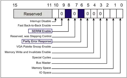
The PCI mechanism for reporting errors is the assertion of PERR# (data parity errors) and SERR# (unrecoverable errors). The PCI Express mechanisms for reporting these events are via the split transaction mechanism (transaction completions) and virtual SERR# signaling via error messages. Configuration Command and Status RegistersFigure 10-6 illustrates the command register and the location of the error-related fields. These bits are set to enable baseline error reporting under control of PCI-compatible software. Table 10-3 defines the specific effects of each bit. Figure 10-6. PCI-Compatible Configuration Command Register
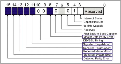
Figure 10-7 illustrates the configuration status register and the location of the error-related bit fields. Table 10-4 on page 374 defines the circumstances under which each bit is set and the actions taken by the device when error reporting is enabled. Figure 10-7. PCI-Compatible Status Register (Error-Related Bits)
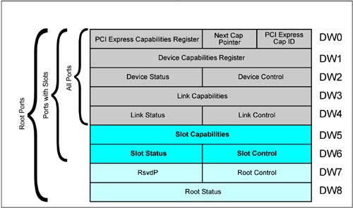
PCI Express Baseline Error HandlingThe Baseline capability also requires use of the PCI Express capability registers. These registers include error detection and handling bit fields that provide finer granularity regarding the nature of an error that is supplied with standard PCI error handling. Figure 10-8 on page 376 illustrates the PCI Express capability register set. These registers provide support for:
Figure 10-8. PCI Express Capability Register Set
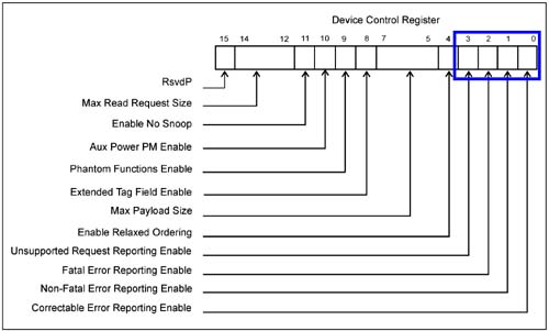
Enabling/Disabling Error ReportingThe Device Control and Device Status registers permit software to enable generation of Error Messages for four error-related events and to check status information to determine which type of error has been detected:
Note that the only specific type of error condition identified is the unsupported request (UR). No granularity is provided for determining other types of error conditions that occur. Only the classification of the error is reported within the device status register. Table 10-5 on page 377 lists each error type and its associated error classification.
Enabling Error Reporting — Device Control RegisterSetting the corresponding bit in the Device Control Register enables the generation of the corresponding Error Message which reports errors associated with each classification. (Refer to Figure 10-9 on page 378.) Unsupported Request errors are specified as Non-Fatal errors and are reported via a Non-Fatal Error Message, but only when the UR Reporting Enable bit is set. Figure 10-9. Device Control Register Bit Fields Related to Error Handling
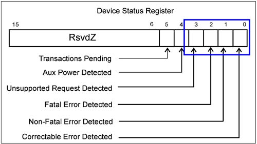
Error Status — Device Status RegisterSee Figure 10-10 on page 379. An error status bit is set any time an error associated with its classification is detected. These bits are set irrespective of the setting of the Error Reporting Enable bits within the Device Control Register. Because Unsupported Request errors are by default considered Non-Fatal Errors, when these errors occur both the Non-Fatal Error status bit and the Unsupported Request status bit will be set. Note that these bits are cleared by software when writing a one (1) to the bit field. Figure 10-10. Device Status Register Bit Fields Related to Error Handling
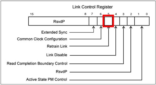
Link ErrorsThe physical link connecting two devices may fail causing a variety of errors. Link failures are typically detected within the physical layer and communicated to the Data Link Layer. Because the link has incurred errors, the error cannot be reported to the host via the failed link. Therefore, link errors must be reported via the upstream port of switches or by the Root Port itself. Also the related fields in the PCI Express Link Control and Status registers are only valid in Switch and Root downstream ports (never within endpoint devices or switch upsteam ports). This permits system software to access link-related error registers on the port that is closest to the host. If software can isolate one or more errors to a given link, one method of attempting to clear a non-correctable error is to retrain the link. The Link Control Register includes a bit that when set forces the Root or Switch port to retrain the link. If transaction (upon completion of the retraining) can once again traverse the link without errors, the problem will have been solved. Figure 10-11 illustrates the Link Control Register and highlights the Retrain Link field that software sets to initiate retaining. Figure 10-11. Link Control Register Allows Retraining of Link
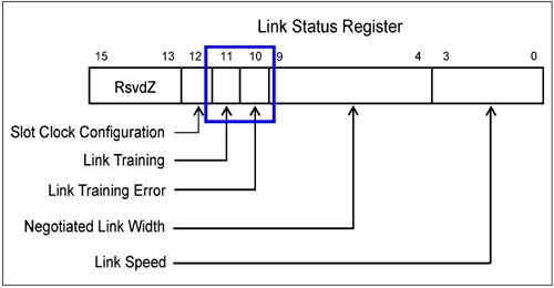
Software can monitor the Link Training bit in the Link Status Register to determine when retraining has completed. Software can also check the Link Training Error bit to verify that link training was successful. Link Training errors are reported via the Fatal Error Message. Figure 10-12 highlights these status bits. Figure 10-12. Link Retraining Status Bits within the Link Status Register
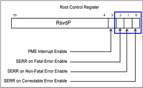
Root's Response to Error MessageWhen a message is received by the Root Complex the action that it takes when reporting the error message to the host system is determined in part by the Root Control Register settings. Figure 10-13 depicts this register and highlights the three bit fields that specify whether an error should be reported as a fatal System Error (SERR set enables generation of a system error). In x86 systems it is likely that a Non-Maskable Interrupt (NMI) will be signaled if the error is to be reported as a SERR. Figure 10-13. Root Control Register
The PME Interrupt Enable bit (3) allows software to enable and disable interrupt generation upon the Root Complex detecting a PME Message transaction. Other options for reporting error messages are not configurable via standard registers. The most likely scenario is that a system interrupt will be signaled to the processor that will call an Error Handler, which may attempt to clear the error condition and/or simply log the error.  |
| [ Team LiB ] |
|