| [ Team LiB ] |


|
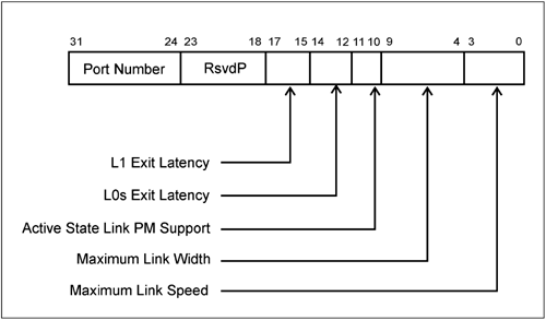
LTSSM Related Configuration RegistersOnly those bits associated with the Link Training and Initialization state are described here. Link Capability RegisterThe Link Capability Register is pictured in Figure 14-21 on page 550 and each bit field is described in the subsections that follow. Figure 14-21. Link Capabilities Register
Maximum Link Speed[3:0]This bit must currently be hard-wired to 0001b, indicating that its supported speed is the Generation 1 Link speed of 2.5Gbits/s. All other encodings are reserved. Maximum Link Width[9:4]This field indicates the maximum width of the PCI Express Link. The values that are defined are:
This register is either hard-wired or is automatically updated by hardware after passing through the Detect state of the LTSSM. This bit cannot be cleared or written by software. Link Status RegisterThe Link Status Register is pictured in Figure 14-22 on page 552 and each bit field is described in the subsections that follow. Link Speed[3:0]:This field is read-only and indicates the negotiated Link speed of the PCI Express Link. It is updated during the Polling state of the LTSSM. Currently, the only defined encoding is 0001b, indicating a Link speed of 2.5Gbits/s. Negotiate Link Width[9:4]This field indicates the result of link width negotiation. There are seven possible widths, all other encodings are reserved. The defined encodings are:
Training Error[10]This bit is set by hardware when a Link Training error has occurred. It is cleared by the hardware upon successful training of the Link when the Link has entered the L0 (active) state. This bit is only supported in upstream devices such as a Root Complex or Switch down stream ports. Link Training[11]This bit is set by the hardware while Link Training is in progress and is cleared when Link Training completes. The LTSSM is either in the Configuration or Recovery state when this bit is set. Link Control RegisterThe Link Control Register is pictured in Figure 14-23 on page 553 and each bit field is described in the subsections that follow. Link DisableWhen set to one, the link is disabled. It is not applicable to and is reserved for Endpoint devices and for an upstream port on a Switch. When this bit is written, any read immediately reflects the value written, regardless of the state of the Link. Writing this bit causes the device to transmit 16 TS Ordered-Sets with the Link Disable bit asserted. Retrain LinkThis bit allows software to initiate Link re-training. This could be used in error recovery. The bit is not applicable to and is reserved for Endpoint devices and the upstream ports of a Switch. When set to one, this directs the LTSSM to the Recovery state before the completion of the Configuration write request is returned. Extended SynchThis bit is used to force the transmission of 4096 FTS (Fast Training Sequence) Ordered-Sets in L0s followed by a single Skip Ordered-Set prior to entering L0. It also forces the transmission of 1024 TS1 Ordered-Sets in L1 prior to entering the Recovery state. This extended sync permits external tools monitoring the link time to achieve Bit and Symbol Lock before the Link enters the L0 or Recovery states and resumes normal communication.  |
| [ Team LiB ] |
|