Primer on Configuration Software
The PCI Bus PM Interface Specification describes how to implement the PCI PM registers that are required in PCI Express. These registers permit the OS to manage the power environment of both PCI and PCI Express functions.
Rather than immediately diving into a detailed nuts-and-bolts description of the PCI Bus PM Interface Specification, it's a good idea to begin by describing where it fits within the overall context of the OS and the system. Otherwise, this would just be a disconnected discussion of registers, bits, signals, etc. with no frame of reference.
Basics of PCI PM
The most popular OSs currently in use on PC-compatible machines are Windows 98/NT/2000/XP. This section provides an overview of how the OS interacts with other major software and hardware elements to manage the power usage of individual devices and the system as a whole. Table 16-1 on page 569 introduces the major elements involved in this process and provides a very basic description of how they relate to each other. It should be noted that neither the PCI Power Management spec nor the ACPI spec (Advanced Configuration and Power Interface) dictate the policies that the OS uses to manage power. It does, however, define the registers (and some data structures) that are used to control the power usage of PCI and PCI Express functions.
Table 16-1. Major Software/Hardware Elements Involved In PC PM|
OS | Directs the overall system power management.To accomplish this goal, the OS issues requests to the ACPI Driver, WDM (Windows Driver Model) device drivers, and to the PCI Express Bus Driver. Application programs that are power conservation-aware interact with the OS to accomplish device power management. | ACPI Driver | Manages configuration, power management, and thermal control of devices embedded on the system board that do not adhere to any industry standard interface specification. Examples could be chipset-specific registers, system board-specific registers that control power planes, etc. The PM registers within PCI Express functions (embedded or otherwise) are defined by the PCI PM spec and are therefore not managed by the ACPI driver, but rather by the PCI Express Bus Driver (see entry in this table). | WDM Device Driver | The WDM driver is a Class driver that can work with any device that falls within the Class of devices that it was written to control. The fact that it's not written for a specific device from a specific vendor means that it doesn't have register and bit-level knowledge of the device's interface. When it needs to issue a command to or check the status of the device, it issues a request to the Miniport driver supplied by the vendor of the specific device.
The WDM also doesn't understand device characteristics that are peculiar to a specific bus implementation of that device type. As an example, the WDM doesn't understand a PCI Express device's configuration register set. It depends on the PCI Express Bus Driver to communicate with PCI Express configuration registers.
When it receives requests from the OS to control the power state of its PCI Express device, it passes the request to the PCI Express Bus Driver:
When a request to power down its device is received from the OS, the WDM saves the contents of its associated PCI Express function's device-specific registers (in other words, it performs a context save) and then passes the request to the PCI Express Bus Driver to change the power state of the device.
Conversely, when a request to re-power the device is received from the OS, the WDM passes the request to the PCI Express Bus Driver to change the power state of the device. After the PCI Express Bus Driver has re-powered the device, the WDM then restores the context to the PCI Express function's device-specific registers. | Miniport Driver | Supplied by the vendor of a device, it receives requests from the WDM Class driver and converts them into the proper series of accesses to the device's register set. | PCI Express Bus Driver | This driver is generic to all PCI Express-compliant devices. It manages their power states and configuration registers, but does not have knowledge of a PCI Express function's device-specific register set (that knowledge is possessed by the Miniport Driver that the WDM driver uses to communicate with the device's register set). It receives requests from the device's WDM to change the state of the device's power management logic:
When a request is received to power down the device, the PCI Express Bus Driver is responsible for saving the context of the function's PCI Express configuration Header registers and any New Capability registers that the device implements. Using the device's PCI Express configuration Command register, it then disables the ability of the device to act as a Requester or to respond as the target of transactions. Finally, it writes to the PCI Express function's PM registers to change its state.
Conversely, when the device must be re-powered, the PCI Express Bus Driver writes to the PCI Express function's PM registers to change its state. It then restores the function's PCI Express configuration Header registers to their original state. | PCI Express PM registers within each PCI Express function's PCI Express configuration space. | The location, format and usage of these registers is defined by the PCI Express PM spec. The PCI Express Bus Driver understands this spec and therefore is the entity responsible for accessing a function's PM registers when requested to do so by the function's device driver (i.e., its WDM). | System Board power plane and bus clock control logic | The implementation and control of this logic is typically system board design-specific and is therefore controlled by the ACPI Driver (under the OS's direction). |
OnNow Design Initiative Scheme Defines Overall PM
A whitepaper on Microsoft's website clearly defines the goals of the OnNow Design Initiative and the problems it addresses. The author has taken the liberty of reproducing the text verbatim from the Goals section of that paper.
Goals
The OnNow Design Initiative represents the overall guiding spirit behind the sought-after PC design. The following are the major goals as stated in an OnNow document:
The PC is ready for use immediately when the user presses the On button. The PC is perceived to be off when not in use but is still capable of responding to wake-up events. Wake-up events might be triggered by a device receiving input such as a phone ringing, or by software that has requested the PC to wake up at some predetermined time. Software adjusts its behavior when the PC's power state changes. The operating system and applications work together intelligently to operate the PC to deliver effective power management in accordance with the user's current needs and expectations. For example, applications will not inadvertently keep the PC busy when it is not necessary, and instead will proactively participate in shutting down the PC to conserve energy and reduce noise. All devices participate in the device power management scheme, whether originally installed in the PC or added later by the user. Any new device can have its power state changed as system use dictates.
System PM States
Table 16-2 on page 572 defines the possible states of the overall system with reference to power consumption. The "Working", "Sleep", and "Soft Off" states are defined in the OnNow Design Initiative documents.
Table 16-2. System PM States as Defined by the OnNow Design Initiative|
Working | The system is completely usable and the OS is performing power management on a device-by-device basis. As an example, the modem may be powered down during periods when it isn't being used. | Sleeping | The system appears to be off and power consumption has been reduced. The sleep levels a system may implement is system design-specific. The amount of time it takes to return to the "Working" state is inversely proportional to the selected level of power conservation. Here are some examples:
The system may keep power applied to main memory, thereby preserving the OS and application programs in memory. The processor's register set contents may also be preserved. In this case, program execution can be resumed very quickly. The system may copy the complete contents of main memory and the processor's register set contents to disk, and then remove power from the processor and main memory. In this case, the restart time will be longer because memory must restore both before resuming program execution.
| Soft Off | The system appears to be off and power consumption has been greatly reduced. It requires a full reboot to return to the "Working" state (because the contents of memory have been lost). | No Power | This state isn't listed in the OnNow Design Initiative documents. The system has been disconnected from its power source. |
Device PM States
The OnNow Design Initiative also defines the PM states at the device level. They are listed and defined in Table 16-4 on page 574. Table 16-3 on page 573 presents the same information in a slightly different form.
Table 16-3. OnNow Definition of Device-Level PM States|
D0 | Device support: Mandatory.
State in which device is on and running. It is receiving full power from the system and is delivering full functionality to the user. This is the initial state entered after a device completes reset. | D1 | Device support: Optional.
Class-specific low-power state (refer to "Device Class-Specific PM Specifications" on page 576) in which device context (see "Definition of Device Context" on page 574) may or may not be lost. | D2 | Device support: Optional.
Class-specific low-power state ("Device Class-Specific PM Specifications" on page 576) in which device context (see "Definition of Device Context" on page 574) may or may not be lost. Attains greater power savings than D1. A device in the D2 state can cause devices to lose some context. | D3 | Device support: Mandatory.
State in which device is off. Device context is lost. Power can be removed from the device. |
Table 16-4. Concise Description of OnNow Device PM States|
D0 | Highest | NA | D1 | < D0 | Faster than D2 | D2 | < D1 | Faster than D3 | D3 | For all intents and purposes, none, although there might be some negligible consumption. | Slowest |
Definition of Device Context
General
During normal operation, the operational state of a device is constantly changing. Software external to the device (e.g., its device driver, the PCI Express Bus Driver, etc.) writes values into some of its registers, reads its status, etc. In addition, the device may contain a processor that executes device-specific code to control the device's interaction with the system as well as with an external element such as a network. The state of the device at a given instant in time is defined by (but not limited to) the following:
The contents of the device's PCI Express configuration registers. The state of the device's IO registers that its device driver interacts with. If the device contains a processor, its current program pointer as well as the contents of some of the processor's other registers.
This is referred to as the current device context. Some or all of this information might be lost if the device's PM state is changed to a more aggressive power conservation level:
If the device is placed in the D1 or D2 state, it may or may not lose some of this context information. If the device is placed in the D3 state, it will lose its context information.
Assume that a device is placed in a more aggressive power conservation state that causes it to lose some or all of its context information. If the device's context information is not restored when the device is placed back in the D0 state (i.e., fully-operational), it will no longer function correctly.
PM Event (PME) Context
Assume that the OS sets up a modem to wake up the system if the phone rings (in other words, on a Ring Detect) and that the system is then commanded to power down by the OS (e.g., in response to the user depressing the power switch). Remember that "power down" is a relative term within the context of power management. The chipset has power applied and monitors the PME# signal. To support this feature, the modem must implement:
A PME (Power Management Event) Message capability. A PME enable/disable control bit. A PME status bit that indicates whether or not the device has send a PME message. One or more device-specific control bits that are used to selectively enable/disable the various device-specific events (such as Ring Detect) that can cause the device to send a PME message. Corresponding device-specific status bits that indicate why the device issued a PME message.
It should be obvious that the modem could not wake the system (by sending a PME message) if the logic described in the bullet list also lost power when the device is commanded to enter the D3 (off) state. It wouldn't "remember" that it was supposed to do so or why, would not be enabled to do so, etc. In other words, for the Ring Detect to successfully wake the system, the device's PME context information must not be lost when the device is placed in the D3 state.
Device Class-Specific PM Specifications
Default Device Class Specification
As mentioned earlier in this chapter, the OnNow Design Initiative provides a basic definition of the four possible power states (D0 - through - D3). It also defines the minimum PM states that all device types must implement. The document that provides this definition is the Default Device Class Power Management spec. This document mandates that all devices, irrespective of device category, must implement the PM states defined in Table 16-5 on page 576.
Table 16-5. Default Device Class PM States|
D0 | Device is on and running. It is receiving full power from the system and is delivering full functionality to the user. | D1 | This state is not defined and not used. | D2 | This state is not defined and not used. | D3 | Device is off and not running. Device context is assumed lost, and there is no need for any of it to be preserved in hardware. This state should consume the minimum power possible. Its only requirement is to recognize a bus-specific command to re-enter D0. Power can be removed from the device while in D3. If power is removed, the device will receive a bus-specific hardware reset upon reapplication of power, and should initialize itself as in a normal power on. |
Device Class-Specific PM Specifications
Above and beyond the power states mandated by the Default Device Class Specification, certain categories (i.e., Classes) of devices may require:
The rules associated with a particular device class are found in a set of documents referred to as Device Class Power Management Specifications. Currently, Device Class Power Management Specifications exist for the following device classes:
Audio Communications Display Input Network PC Card Storage
They are available on Microsoft's Hardware Developers' web site.
Power Management Policy Owner
General
A device's PM policy owner is defined as the software module that makes decisions regarding the PM state of a device.
In Windows OS Environment
In a Windows environment, the policy owner is the class-specific driver (i.e., the WDM) associated with devices of that class.
PCI Express Power Management vs. ACPI
PCI Express Bus Driver Accesses PCI Express Configuration and PM Registers
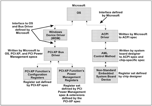
As indicated in Table 16-1 on page 569 and Figure 16-1 on page 578, the PCI Express Bus Driver understands the location, format and usage of the PM registers defined in the PCI Power Management spec. It therefore is the software entity that is called whenever the OS needs to change the power state of a PCI Express device (or to determine its current power state and capabilities), or to access its configuration registers. Likewise,
The IEEE 1394 Bus Driver understands the location, format and usage of the PM registers defined in the 1394 Power Management spec. The USB Bus Driver understands the location, format and usage of the PM registers defined in the USB Power Management spec.
Note that a discussion of the 1394 and USB Bus drivers is outside the scope of this book.
ACPI Driver Controls Non-Standard Embedded Devices
There are devices embedded on the system board whose register sets do not adhere to any particular industry standard spec. At boot time, the BIOS reports these devices to the OS via a set of tables (the ACPI tables; also referred to as the namespace; ACPI stands for Advanced Configuration and Power Interface). When the OS needs to communicate with any of these devices, it calls the ACPI Driver. The ACPI Driver executes a handler (referred to as a Control Method) associated with the device. The handler is found in the ACPI tables that were passed to the OS by the BIOS at boot time. The handler is written by the system board designer in a special interpretive language referred to as ACPI Source Language, or ASL. The format of ASL is defined in the ACPI spec. The ASL source is then compiled into ACPI Machine Language, or AML. Note that AML is not a processor-specific machine language. It is a tokenized (i.e., compressed) version of the ASL source code. The ACPI Driver incorporates an AML token interpreter that enables it to "execute" a Control Method.
A discussion of ACPI is outside the scope of this book. It is only mentioned because the OS uses a combination of ACPI and Bus Driver services (such as the PCI Express (PCI-XP) Bus Driver) to manage the system's power and configuration.
Some Example Scenarios
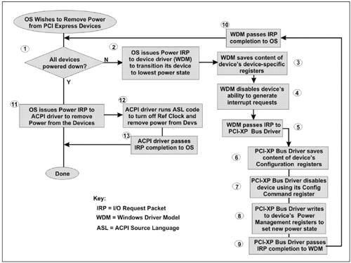
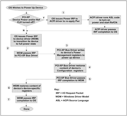
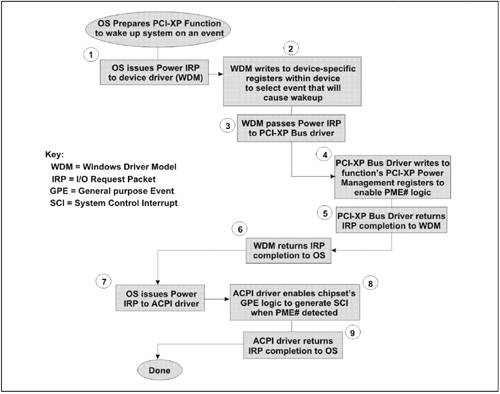
Figure 16-2 on page 581, Figure 16-3 on page 583, and Figure 16-4 on page 584 illustrate some example PM scenarios. It should be noted that these illustrations are meant to be introductory in nature and do not cover all possible power state changes. The examples focus on turning a PCI Express function Off (from a power perspective), or turning it On. This implies two possible states for a device (D0 and D3). While it's possible a function only has two states, a function may additionally implement other optional, intermediate power states (D1 and/or D2). The possible power states are discussed later in this chapter.
The following are some of the terms used in the illustrations:
IO Request Packet, or IRP.
The OS communicates a request to a Windows device driver by issuing an IRP to it. There are different categories of IRPs; for example, a Power IRP is used to request a change in the PM state of a device to or get its current PM state.
Windows Driver Model, or WDM.
A device driver written for the Windows environment that controls a device or a group of similar devices (e.g., network adapters).
General Purpose Event, or GPE.
ACPI-related events. The chipset implements a GPE register which is used to selectively enable or disable recognition of various GPEs. When recognition of a specific GPE is enabled (such as a PM event) and that event occurs, the chipset generates an SCI (System Control Interrupt) to the processor. This invokes the GPE handler within the ACPI Driver which then reads the GPE Status registers in the chipset to determine which GPE caused the interrupt.
System Control Interrupt, or SCI.
A system interrupt used by hardware to notify the OS of ACPI events. The SCI is an active low, shareable, level-sensitive interrupt.
Control Method.
A Control Method is a definition of how the OS can perform a simple hardware task. For example, the OS invokes a Control Method to read the temperature of a thermal zone. See the definition of ASL. An ACPI-compatible system must provide a minimal set of common Control Methods in the ACPI tables. The OS provides a set of well-defined Control Methods that ACPI table developers can reference in their Control Methods. OEMs can support different revisions of chipsets with one BIOS by either including Control Methods in the BIOS that test configurations and respond as needed or by including a different set of Control Methods for each chipset revision.
ACPI Source Language, or ASL.
Control Methods are written in a language called ASL which is then compiled into AML (ACPI Machine Language). AML is comprised of a highly-compressed series of tokens that represent the ASL code. The AML code is interpreted and executed by an AML interpreter incorporated within the ACPI Driver.
Scenario—OS Wishes To Power Down PCI Express Devices
Figure 16-2 on page 581 illustrates the basic series of actions required when the OS wishes to power down all PCI Express devices and associated links in the fabric (i.e., remove the reference clock and Vcc) to conserve maximum power. Before doing this, it must first ensure that all functions within all PCI Express devices have been powered down.
If all of the PCI functions within all PCI Express devices are already powered down, skip to step 11. The OS issues a Power IRP to the device driver (WDM) to transition all device functions to the lowest power state. The WDM saves the current content of the functions device-specific registers. The WDM disables the device's ability to generate interrupt requests by clearing its interrupt enable bit in its function-specific register set. The WDM passes the Power IRP to the PCI Express Bus Driver. The Bus Driver saves the current content of the function's configuration Header registers and any New Capability register sets that it may implement, along with extended configuration registers. The PCI Express Bus Driver disables the function's ability to act as a Requester and Completer by clearing the appropriate bits in its configuration Command register. The PCI Express Bus Driver writes to the function's PCI PM registers to set the lowest power state (off). The PCI Express Bus Driver passes an IRP completion notice to the WDM. The WDM passes the IRP completion notice to the OS. Steps 2-through-10 are repeated until all PCI functions within all devices have been placed in the powered down state. The OS issues a Power IRP to the ACPI driver requesting that it turn off the reference clock and Vcc. The ACPI driver runs the appropriate AML Control Method to turn off the clock and power. The ACPI driver passes the IRP completion notice to the OS.
Scenario—Restore All Functions To Powered Up State
Figure 16-3 on page 583 illustrates the basic series of actions required when the OS wishes to power up a PCI Express function that was placed in the powered down state earlier.
It's possible that the OS had removed power to all PCI Express devices and turned off the PCI Express reference clock as in the previous example. To restore function back to their operating condition, the OS issues a Power (i.e., Power Management) IRP to the ACPI Driver requesting that the links be turned back on. In response, the ACPI Driver would execute the AML code necessary to turn on the PCI Express reference clock generator and re-apply power to the devices. It should be obvious that PCI-XP devices closest to the Host Bridge/Root Complex must be powered up first. When the ACPI Driver has completed this operation, it issues an IRP completion notice back to the OS. If the reference clock and power had not been turned off earlier, this step can be skipped. The OS issues a Power IRP to the PCI Express device's WDM requesting that the device be restored to the full power state. The WDM passes the IRP to the PCI Express Bus Driver. The PCI Express Bus Driver writes to the device's PCI Express PM registers to power up device. The PCI Express Bus Driver restores the contents of the device's PCI Express configuration Header registers and any New Capability register sets that the device implements. This automatically restores the device's PCI Express configuration Command register enable bits to their original states. The PCI Express Bus Driver passes an IRP completion notice back to the WDM. The WDM restores the content of the device's device-specific IO or memory-mapped IO registers. This causes the device's interrupt enable bit to be restored, re-enabling the device's ability to generate interrupt requests. The device is now ready to resume normal operation. The WDM returns an IRP completion notice to the OS.
Scenario—Setup a Function-Specific System WakeUp Event
Figure 16-4 on page 584 illustrates the OS preparing a PCI Express device so that it will wake up the system (send a PME message) when a particular device-specific event occurs.
The OS issues a Power IRP to the device driver (WDM) to enable the device to wake up the system on a specified event. The WDM writes to device-specific registers within the device to enable the event that will cause the system to wake up. The WDM passes the IRP to the PCI Express Bus driver. The PCI Express Bus Driver writes to the function's PM registers to enable its PME# logic. The PCI Express Bus Driver returns the IRP completion notice to the WDM. The WDM returns the IRP completion notice to the OS. The OS issues a Power IRP to the ACPI driver requesting that the PCI Express Power Management Event (PME) monitoring logic be enabled to generate an ACPI interrupt (referred to as an SCI, or System Control Interrupt). The ACPI driver enables the chipset's GPE logic to generate an SCI when PME# is detected asserted. The ACPI driver returns the IRP completion notice to the OS.
 |

