Execution of Initialization Code
Prior to the discovery of the device's ROM, the configuration software has accomplished the following:
Assigned one or more memory and/or IO ranges to the function by programming its Base Address Registers (see "Base Address Registers" on page 792). If the device is interrupt-driven, the interrupt routing information has been programmed into the device's Interrupt Line register (see "Interrupt Line Register" on page 791). In addition, if the UDF bit (this bit was in the 2.1 PCI spec and was deleted from the 2.2 PCI spec) was set in the device's configuration Status register, the user has been prompted to insert the diskette containing the PCI configuration file, or PCF, and the user selected any configuration options available from the file.
After the ROM is discovered, the configuration software copied a code image from the ROM into RAM memory. After the appropriate code image has been copied into system memory, the device ROM's address decoder is disabled. The configuration software must keep the area of RAM (the image resides in) read/writable. The sequence that follows assumes that the selected ROM image's Code Type field is 00h and that the device resides on a PC compatible platform. The configuration software then executes the following sequence:
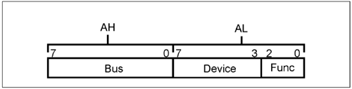
Refer to Figure 23-5 on page 888. The software calls the initialization module within the image (through location 3h in the image), supplying it with three parameters in the AX register: the bus number, device number and function number of the function associated with the ROM:
- The 8-bit bus number is supplied in AH, - the device number is supplied in the upper five bits of AL, - and the function number in the lower three bits of AL.
It's necessary to supply the initialization code with this information so that it can determine how the function has been configured. For example, what IO and/or memory address range the configuration software has allocated to the function (via its base address registers), what input on the interrupt controller the function's interrupt pin has been routed to, etc. The initialization code then issues a call to the PCI BIOS, supplying the bus number, device number, and function number as input parameters and requesting the contents of the function's Base Address Registers. Armed with this information, the initialization code can now communicate with the function's IO register set to initialize the device and prepare it for normal operation. If the ROM image has a device-specific Interrupt Service Routine embedded within the run-time module, it reads from the device's Interrupt Line configuration register to determine which system interrupt request input on the interrupt controller the function's PCI interrupt pin has been routed to by the configuration software. Using this routing information, the initialization code knows which entry in the interrupt table in memory must be hooked. It first reads the pointer currently stored in that interrupt table entry and saves it within the body of the run-time portion of the image. It then stores the pointer to the interrupt service routine embedded within the run-time module of the code image into that interrupt table entry. In this way, it maintains the integrity of the interrupt chain. Since the area of system memory it has been copied into must be kept read/writable until the initialization code completes execution, the initialization code has no problem saving the pointer that it read from the interrupt table entry before hooking it to its own service routine. The ROM image may also have a function-specific BIOS routine embedded within the run-time module of the code image. In this case, it needs to hook another interrupt table entry to this BIOS routine. Once again, it reads and saves the pointer currently stored in that interrupt table entry and then stores the pointer to the BIOS routine embedded within the run-time module of the code image. In this way, it maintains the integrity of the interrupt chain. Note regarding steps 3 and 4: This procedure is different if the function will deliver interrupts via MSI instead of INTx messages. It would read the MSI capability structure of the function for the message address and message data fields and use that info to find the interrupt table entry. Then it would store the pointer to the interrupt service routine embedded within the run-time module of the code image into that interrupt table entry. No interrupt chaining would have to be supported. Since the area of system memory it resides in must be kept read/writable until the initialization code completes execution, the initialization code can adjust the code image length (in location 2h of the image). Very typically, at the completion of initialization code execution the programmer will adjust the image length field to encompass the area from the image's start through the end of the run-time code. The initialization code is typically only executed once and is then discarded. It must also recompute a new Checksum and store it at the end of the run-time code. If it sets the image length to zero, it doesn't need to recompute the image checksum and update it. When it returns control to the configuration software, a length of zero would indicate that the driver will not be used for some reason (perhaps a problem was detected during the setup of the device) and all of the memory it occupies can be deallocated and reused for something else. Once the initialization code has completed execution, it executes a return to the system software that called it.
The configuration software then performs two final actions:
It interrogates the image size (at offset 2h in the image) to determine if it was altered. If it has, the configuration software adjusts the amount of memory allocated to the image to make more efficient use of memory. The image is typically shorter than it was. It computes a new checksum for the image and stores it at the end of the image. Write-protects the area of main memory the image resides in. This will keep the OS from using the area after it takes control of the machine.
The ISA Plug-and-Play spec refers to the PCI method of writing device ROM code and handling its detection, shadowing, and initialization, as the DDIM (Device Driver Initialization Model). That spec stresses that this is the model that all device ROMs for other buses (i.e., other than PCI) should adhere to.
|

