Check out my first novel, midnight's simulacra!
InaMORata 2.0

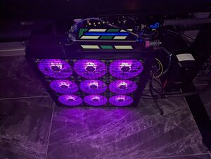
In 2024, I redesigned the InaMORAta to use 5v ARGB fans (the previous design used 12v RGB fans). I also significantly simplified the electronics. We get a single tachometer signal from the 9x fans, and a tachometer signal from both pumps. Similarly, we control all 9x fans with a single PWM signal, and control the pumps independently with two more. We control the fans' LEDs as three series of 36 LEDs each, each corresponding to a row of three fans. We measure and report ambient temperature. A distinct sensor provides visual display of speed and coolant temperature. The total cost runs between $600 and $800, and is easily capable of cooling a remote 2kW machine. It's by no means a great value, but watercooling rarely is.
Inputs to the inaMORata are a 12V AC adapter and a G¼" tube of hot coolant. Outputs are heat, light, and a G¼" tube of cooled coolant. Additionally, MQTT over IP over WiFi provides control and report.
Components
- Mo-Ra3 420mm radiator plus front cover
- 9x 140mm Arctic P14 ARGB 140mm fans
- 12V AC adapter rated for at least 9A (108W)
- 12V->5V buck converter rated for at least 5A (25W) output
- CODI6 (controls ARGB, distributes 12V+5V power to fans)
- 2x SATA splitters
- One SATA power cable (4 wires)
- 4x heatshrink solder tubes
- EKWB EK-XTOP dual D5 pump
- Perfboard, onto which is soldered:
- Espressif ESP-WROOM-32S microcontroller (controls fans, sensors, provides MMQT+WiFi)
- 4.7kΩ resistor
- 3x 0.1nF ceramic capacitors
- 3x 10kΩ resistors
- 3x 3.3kΩ resistors
- 3x Molex 4-pin fan headers
- DS18B20 digital thermistor
- USB-C header with pigtails
- G¼" transducer/thermistor with visual display (optional)
You'll need a hot air gun and a soldering iron (plus whatever you use to assemble the Mo-Ra, and attach things to it).
Microelectronics
- Solder the ESP32 onto the perfboard
- Solder the 3x Molex 4-pin fan headers onto the perfboard
- It's best to solder all 4 pins, but you must solder the last two
- Wire the 3V3 and GND pins of the ESP32 to the right side's +/- channels
For PWM speed control
- Wire the fourth pin (PWM) of each fan header to pins 33, 32, and 25 on the ESP32
For tachometry
- Wire the third pin (tach) of each fan header to the other side of the perfboard
- Solder a 10kΩ resistor to the + channel to the tach pin's row
- Solder a 3.3kΩ resistor from each tach pin's row down to the next row
- Solder a 0.1nF capacitor from each of these rows to the - channel
- Wire these same rows to pins 5, 22, and 23 on the ESP32
For ambient temp sensing
- Solder a 4.7kΩ resistor from the + channel to some row
- Wire this row to pin 4 on the ESP32
- Solder the yellow (data) wire of the DS18B20 to this same row
- Solder the black (ground) wire of the DS18B20 to the - channel
- Solder the black (ground) wire of the DS18B20 to the + channel
Power
We have power requirements at both 12V and 5V, ultimately sourced at 12V. The 12 LEDs of each PF-14 take 0.4A at 5V. With 9 of them, that's 18W. The ESP32 will also draw 5V, but not more than a watt. Assume 90% efficiency for a total of 20.4 input watts. At 12V, we have 23W to each of our pumps (46W total). Each fan takes 0.17A of 12V, and thus 9 draw 18.36W. That's 64.36W and 20.4W, a total of 84.76W. 85W at 12V requires just over 7A.
- 12V AC adapter runs to barreljack on/off switch
- On/off switch takes 12V to SATA and buck converter
- The two sets of three wires are connected with two heatshrink solder tubes
- Buck converter takes 5V to SATA and USB-C pigtails
- The two sets of three wires are connected with two heatshrink solder tubes
- USB-C takes 5V to ESP32
- SATA takes 12V+5V to SATA splitter
- SATA splitter takes 12V+5V to CODI6 + SATA splitter
- SATA splitter takes 12V to 2x pumps
- CODI6 takes 12V (via fan hookup) and 5V (via ARGB hookup) to 3x rightmost fans
- 3x rightmost fans take 12V+5V to corresponding 3x middle fans
- 3x middle fans takes 12V+5V to corresponding 3x leftmost fans
We don't need to expose the 5V to the pumps, but it doesn't hurt anything. The CODI6 has a 5-pin wire, where three pins (12V, 5V, ground) go to a SATA connector, and two pins (tach, pwm) go to a 4-hole Molex fan connector. This connector doesn't carry 12V or ground like a 4-wire Molex would.
At this point, we have three hookups unconnected: the three Molex 4-hole connectors coming off the pumps and CODI6. Each has a tach and PWM signal, and none are drawing power. Hook them up to the perfboard's Molex 4-pin headers.