Introduction to the Flow Control Mechanism
The specification defines the requirements of the Flow Control mechanism by describing conceptual registers and counters along with procedures and mechanisms for reporting, tracking, and calculating whether a transaction can be sent. These elements define the functional requirements; however, the actual implementation may vary from the conceptual model. This section introduces the specified model that serves to explain the concept and define the requirements. The approach taken focuses on a single flow control example for a non-posted header. The concepts discussed apply to all Flow Control buffer types.
The Flow Control Elements
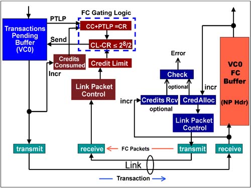
Figure 7-3 identifies and illustrates the elements used by the transmitter and receiver when managing flow control. This diagram illustrates transactions flowing in a single direction across a link, but of course another set of these elements is used to support transfers in the opposite direction. The primary function of each element within the transmitting and receiving devices is listed below. Note that for a single direction these Flow Control elements are duplicated for each Flow Control receive buffer, yielding six sets of elements. This example deals with non-posted header flow control.
Transmitter Elements
Pending Transaction Buffer —
holds transactions that are pending transfer within the same virtual channel.
Credit Consumed Counter —
tracks the size of all transactions sent from the VC buffer (of the specified type, e.g., non-posted headers) in Flow Control credits. This count is abbreviated "CC."
Credit Limit Register —
this register is initialized by the receiving device when it sends Flow Control initialization packets to report the size of the corresponding Flow Control receive buffer. Following initialization, Flow Control update packets are sent periodically to add more Flow Control credits as they become available at the receiver. This value is abbreviated "CL."
Flow Control Gating Logic —
performs the calculations to determine if the receiver has sufficient Flow Control credits to receive the pending TLP (PTLP). In essence, this check ensures that the total CREDITS_CONSUMED (CC) plus the credit required for the next packet pending transmission (PTLP) does not exceed the CREDIT_LIMIT (CL). This specification defines the following equation for performing the check, with all values represented in credits: CL – (CC + PTLP )mod2[FieldSize]  2[FieldSize ]/2 2[FieldSize ]/2
For an example application of this equation, See "Stage 1 — Flow Control Following Initialization" on page 294.
Receiver Elements
Flow Control (Receive) Buffer —
stores incoming header or data information.
Credit Allocated —
This counter tracks the total Flow Control credits that have been allocated (made available) since initialization. It is initialized by hardware to reflect the size of the associated Flow Control buffer. As the buffer fills the amount of available buffer space decreases until transactions are removed from the buffer. The number of Flow Control credits associated with each transaction removed from the buffer is added to the CREDIT_ALLOCATED counter; thereby keeping a running count of new credits made available.
Credits Received Counter (optional) —
this counter keeps track of the total size of all data received from the transmitting device and placed into the Flow Control buffer (in Flow Control credits). When flow control is functioning properly, the CREDITS_RECEIVED count should be the same as CREDITS_CONSUMED count at the transmitter and be equal to or less than the CREDIT_ALLOCATED count. If this is not true, then a flow control buffer overflow has occurred and error is detected. Although optional the specification recommends its use.
Flow control management is based on keeping track of Flow Control credits using modulo counters. Consequently, the counters are designed to role over when the count saturates. The width of the counters depend on whether flow control is tracking transaction headers or data:
In addition, all calculations are made using unsigned arithmetic. The operation of the counters and the calculations are explained by example on page 290.
 |

