Enumerating a System With a Single Root Complex
Figure 21-2 on page 748 illustrates an example system before the buses and devices have been enumerated, while Figure 21-3 on page 749 shows the same system after the buses and devices have been enumerated. The discussion that follows assumes that the configuration software uses either of the two configuration mechanisms defined in the previous chapter. At startup time, the configuration software executing on the processor performs bus/device/function enumeration in the following manner:
Starting with device 0 (bridge A), the enumeration software attempts to read the Vendor ID from function 0 in each of the 32 possible devices on bus 0. If a valid (not FFFFh) Vendor ID is returned from bus 0, device 0, function 0, this indicates that the device is implemented and contains at least one function. Proceed to the next step. If a value of FFFFh were returned as the Vendor ID, this would indicate that function 0 is not implemented in device 0. Since it is a rule that the first function implemented in any device must be function 0, this would mean that device was not implemented and the enumeration software would proceed to probe bus 0, device 1, function 0.
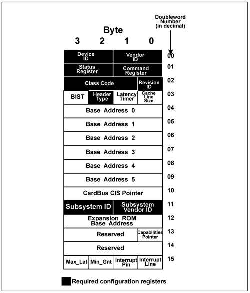
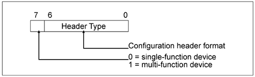
The Header Type field (see Figure 21-6 and Figure 21-7) in the Header register (see Figure 21-4) contains the value one (0000001b) indicating that this is a PCI-to-PCI bridge with the PCI-compatible register layout shown in Figure 21-7 on page 752. This discussion assumes that the Multifunction bit (bit 7) in the Header Type register is 0, indicating that function 0 is the only function in this bridge. It should be noted that the spec does not preclude implementing multiple functions within this bridge and each of these functions, in turn, could represent virtual PCI-to-PCI bridges.
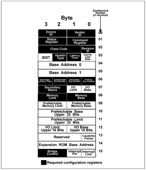
Software now performs a series of configuration writes to set the bridge's bus number registers as follows: Primary Bus Number Register = 0. Secondary Bus Number Register = 1. Subordinate Bus Number Register = 1.
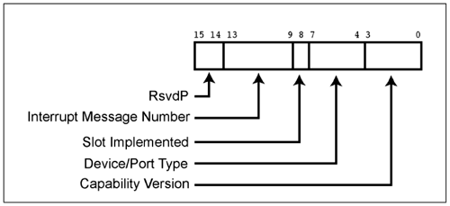
The bridge is now aware that the number of the bus directly attached to its downstream side is 1 (Secondary Bus Number = 1) and the number of the bus farthest downstream of it is 1 (Subordinate Bus Number = 1). Software updates the Host/PCI bridge's Subordinate Bus Number register to 1. The enumeration software reads bridge A's Capability Register (Figure 21-5 on page 750 and Table 21-1 on page 753; a detailed description of this register can be found in "PCI Express Capabilities Register" on page 898). The value 0100b in the register's Device/Port Type field indicates that this a Root Port on the Root Complex.
The specification states that the enumeration software must perform a depth-first search, so before proceeding to discover additional functions/devices on bus 0, it must proceed to search bus 1. Software reads the Vendor ID of bus 1, device 0, function 0. A valid Vendor ID is returned, indicating that bus 1, device 0, function 0 exists. The Header Type field in the Header register contains the value one (0000001b) indicating that this is a PCI-to-PCI bridge. In addition, bit 7 is a 0, indicating that bridge C is a single-function device. Bridge C's Capability Register contains the value 0101b in the Device/Port Type field indicating that this is the upstream Port on a switch. Software now performs a series of configuration writes to set bridge C's bus number registers as follows: Primary Bus Number Register = 1. Secondary Bus Number Register = 2. Subordinate Bus Number Register = 2.
Bridge C is now aware that the number of the bus directly attached to its downstream side is 2 (Secondary Bus Number = 2) and the number of the bus farthest downstream of it is 2 (Subordinate Bus Number = 2). Software updates the Subordinate Bus Number registers in the Host/PCI bridge and in bridge A to 2. Continuing with its depth-first search, a read is performed from bus 2, device 0, function 0's Vendor ID register. The example assumes that bridge D is device 0, function 0 on bus 2. A valid Vendor ID is returned, indicating that bus 2, device 0, function 0 exists. The Header Type field in the Header register contains the value one (0000001b) indicating that this is a PCI-to-PCI bridge. In addition, bit 7 is a 0, indicating that bridge D is a single-function device. Bridge D's Capability Register contains the value 0110b in the Device/Port Type field indicating that this is the downstream Port on a switch. Software now performs a series of configuration writes to set bridge D's bus number registers as follows: Primary Bus Number Register = 2. Secondary Bus Number Register = 3. Subordinate Bus Number Register = 3.
Bridge D is now aware that the number of the bus directly attached to its downstream side is 3 (Secondary Bus Number = 3) and the number of the bus farthest downstream of it is 3 (Subordinate Bus Number = 3). Software updates the Subordinate Bus Number registers in the Host/PCI bridge, bridge A, and bridge C to 3. Continuing with its depth-first search, a read is performed from bus 3, device 0, function 0's Vendor ID register. A valid Vendor ID is returned, indicating that bus 3, device 0, function 0 exists. The Header Type field in the Header register contains the value zero (0000000b) indicating that this is an Endpoint device. In addition, bit 7 is a 1, indicating that this is a multifunction device. The device's Capability Register contains the value 0000b in the Device/Port Type field indicating that this is an Endpoint device. The enumeration software performs accesses to the Vendor ID of functions 1-through-7 in bus 3, device 0 and determines that only function 1 exists in addition to function 0. Having exhausted the current leg of the depth first search, the enumeration software backs up one level (to bus 2) and moves on to read the Vendor ID of the next device (device 1). The example assumes that bridge E is device 1, function 0 on bus 2. A valid Vendor ID is returned, indicating that bus 2, device 1, function 0 exists. The Header Type field in bridge E's Header register contains the value one (0000001b) indicating that this is a PCI-to-PCI bridge. In addition, bit 7 is a 0, indicating that bridge E is a single-function device. Bridge E's Capability Register contains the value 0110b in the Device/Port Type field indicating that this is the downstream Port on a switch. Software now performs a series of configuration writes to set bridge E's bus number registers as follows: Primary Bus Number Register = 2. Secondary Bus Number Register = 4. Subordinate Bus Number Register = 4.
Bridge E is now aware that the number of the bus directly attached to its downstream side is 4 (Secondary Bus Number = 4) and the number of the bus farthest downstream of it is 4 (Subordinate Bus Number = 4). Software updates the Subordinate Bus Number registers in the Host/PCI bridge, bridge A, and bridge C to 4. Continuing with its depth-first search, a read is performed from bus 4, device 0, function 0's Vendor ID register. A valid Vendor ID is returned, indicating that bus 4, device 0, function 0 exists. The Header Type field in the Header register contains the value zero (0000000b) indicating that this is an Endpoint device. In addition, bit 7 is a 0, indicating that this is a single-function device. The device's Capability Register contains the value 0000b in the Device/Port Type field indicating that this is an Endpoint device. Having exhausted the current leg of the depth first search, the enumeration software backs up one level (to bus 2) and moves on to read the Vendor ID of the next device (device 2). The example assumes that devices 2-through-31 are not implemented on bus 2, so no additional devices are discovered on bus 2. The enumeration software backs up to the bus within the Root Complex (bus 0) and moves on to read the Vendor ID of the next device (device 1). The example assumes that bridge B is device 1, function 0 on bus 0. In the same manner as previously described, the enumeration software discovers bridge B and performs a series of configuration writes to set bridge B's bus number registers as follows: Primary Bus Number Register = 0. Secondary Bus Number Register = 5. Subordinate Bus Number Register = 5.
Bridge B is now aware that the number of the bus directly attached to its downstream side is 5 (Secondary Bus Number = 5) and the number of the bus farthest downstream of it is 5 (Subordinate Bus Number = 5). The Host/PCI's Subordinate Bus Number is updated to 5. Bridge F is then discovered and a series of configuration writes are performed to set its bus number registers as follows: Primary Bus Number Register = 5. Secondary Bus Number Register = 6. Subordinate Bus Number Register = 6.
Bridge F is now aware that the number of the bus directly attached to its downstream side is 6 (Secondary Bus Number = 6) and the number of the bus farthest downstream of it is 6 (Subordinate Bus Number = 6). The Host/PCI bridge's and bridge B' Subordinate Bus Number registers are updated to 6. Bridge G is then discovered and a series of configuration writes are performed to set its bus number registers as follows: Primary Bus Number Register = 6. Secondary Bus Number Register = 7. Subordinate Bus Number Register = 7.
Bridge F is now aware that the number of the bus directly attached to its downstream side is 7 (Secondary Bus Number = 7) and the number of the bus farthest downstream of it is 7 (Subordinate Bus Number = 7). The Host/PCI bridge's Subordinate Bus Number register is updated to 7. Bridge B's and F's Subordinate Bus Number registers are also updated to 7. A single-function Endpoint device is discovered at bus 7, device 0, function 0. Bridge H is then discovered and a series of configuration writes are performed to set its bus number registers as follows: Primary Bus Number Register = 6. Secondary Bus Number Register = 8. Subordinate Bus Number Register = 8.
Bridge F is now aware that the number of the bus directly attached to its downstream side is 8 (Secondary Bus Number = 8) and the number of the bus farthest downstream of it is 8 (Subordinate Bus Number = 8). The Host/PCI bridge's Subordinate Bus Number register is updated to 8. Bridge B's and F's Subordinate Bus Number registers are also updated to 8. Bridge J is discovered and its Capability register's Device/Port Type fields identifies it as a PCI Express-to-PCI bridge. A series of configuration writes are performed to set bridge J's bus number registers as follows: Primary Bus Number Register = 8. Secondary Bus Number Register = 9. Subordinate Bus Number Register = 9.
Bridge F is now aware that the number of the bus directly attached to its downstream side is 9 (Secondary Bus Number = 9) and the number of the bus farthest downstream of it is 9 (Subordinate Bus Number = 9). The Host/PCI bridge's Subordinate Bus Number register is updated to 9. Bridge B's, bridge F's, and bridge H's Subordinate Bus Number registers are also updated to 9. All devices and their respective functions on bus 9 are discovered and none of them are bridges. Bridge I is then discovered and a series of configuration writes are performed to set its bus number registers as follows: Primary Bus Number Register = 6. Secondary Bus Number Register = 10. Subordinate Bus Number Register = 10.
Bridge I is now aware that the number of the bus directly attached to its downstream side is 10 (Secondary Bus Number = 10) and the number of the bus farthest downstream of it is 10 (Subordinate Bus Number = 10). The Host/PCI bridge's Subordinate Bus Number register is updated to 10. Bridge B's and bridge F's Subordinate Bus Number registers are also updated to 10. A single-function Endpoint device is discovered at bus 10, device 0, function 0.
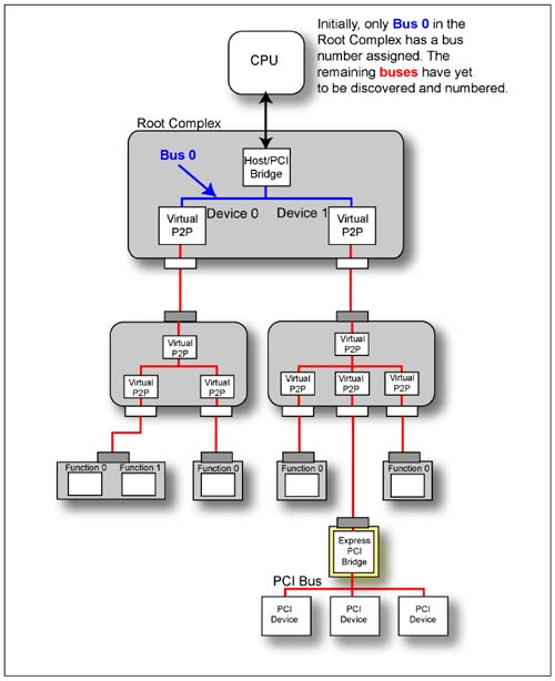
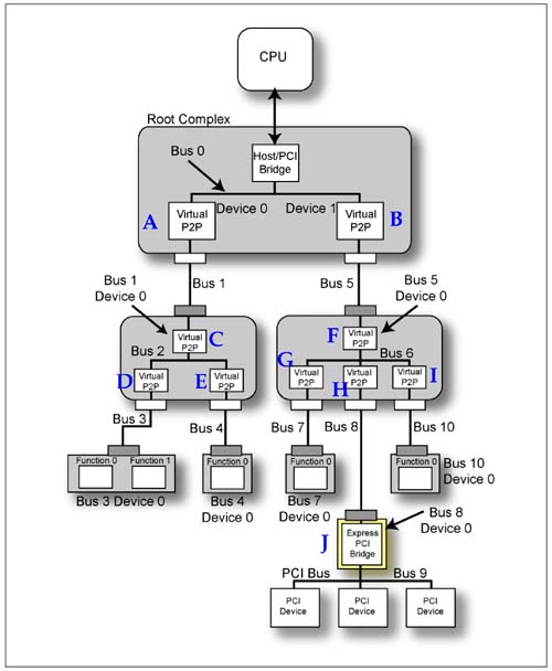
Table 21-1. Capability Register's Device/Port Type Field Encoding|
0000b | PCI Express Endpoint device. | 0001b | Legacy PCI Express Endpoint device. | 0100b | Root Port of PCI Express Root Complex. This value is only valid for devices/functions that implement a Type 01h PCI Configuration Space header. | 0101b | Upstream Port of PCI Express Switch. This value is only valid for devices/functions that implement a Type 01h PCI Configuration Space header. | 0110b | Downstream Port of PCI Express Switch. This value is only valid for devices/functions that implement a Type 01h PCI Configuration Space header. | 0111b | PCI Express-to-PCI/PCI-X Bridge. This value is only valid for devices/functions that implement a Type 01h PCI Configuration Space header. | 1000b | PCI/PCI-X to PCI Express Bridge. This value is only valid for devices/functions that implement a Type 01h PCI Configuration Space header. | All other encodings are reserved. |
 |

