Enumerating a System With Multiple Root Complexes
Refer to Figure 21-8 on page 757. In a system with multiple Root Complexes, each Root Complex:
Implements the Configuration Address Port and the Configuration Data Port at the same IO addresses (if it's an x86-based system). Implements the Enhanced Configuration Mechanism. Contains a Host/PCI bridge. Implements the Bus Number and Subordinate Bus Number registers at separate addresses known to the configuration software.
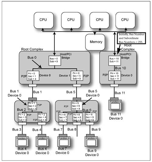
In the example illustration, each Root Complex is a member of the chipset and one of them is designated as the bridge to bus 0 (let's call this the primary Root Complex) while the other one is designated as the bridge to bus 255 (bus FFh; let's call it the secondary Root Complex). The default Bus Number and Subordinate Bus Number register values at startup time are:
In the primary Root Complex, both the Bus Number and Subordinate Bus Number registers are set to 0. In the secondary Root Complex, both the Bus Number and Subordinate Bus Number registers are set to FFh (255d).
Operational Characteristics of the PCI-Compatible Mechanism
In order to prevent contention on the processor's FSB signals, only one of the bridges responds to the processor's accesses to the configuration ports:
When the processor initiates the IO write to the Configuration Address Port, only one of the Host/PCI bridges (typically the one in the primary Root Complex) actively participates in the transaction. The other bridge quietly snarfs the data as it's written to the active participant. Both bridges then compare the target bus number to their respective Bus Number and Subordinate Bus Number registers. If the target bus doesn't reside behind a particular Host/PCI bridge, that bridge doesn't convert the subsequent access to its Configuration Data Port into a configuration access on its bus (in other words, it ignores the transaction). A subsequent read or write access to the Configuration Data Port is only accepted by the Host/PCI bridge that is the gateway to the target bus. This bridge responds to the processor's transaction and the other ignores it. When the access is made to the Configuration Data Port, the selected bridge tests the state of the Enable bit in its Configuration Address Port. If the Enabled bit = 1, the bridge converts the processor's IO access into a configuration access: If the target bus is the bus immediately on the other side of the Host/PCI bridge, the bridge converts the access to a Type 0 configuration access on its secondary bus. Otherwise, it converts it into a Type 1 configuration access.
Operational Characteristics of the Enhanced Configuration Mechanism
In order to prevent contention on the processor's FSB signals, only one of the bridges responds to the processor's accesses to the enhanced configuration memory-mapped IO space:
When the processor initiates a memory-mapped IO access to a memory location within the enhanced configuration memory-mapped IO address range, the Host/PCI bridges in each Root Complex examines address bits A[27:20] to determine the target bus number. The bridge wherein the target bus falls within the range of buses downstream of that bridge (as defined by the contents of its Bus Number and Subordinate Bus Number registers) acts as the target of the processor's FSB transaction while the other bridge does not actively participate in the transaction. The bridge with a bus compare converts the processor's memory access into a configuration access: If the target bus is the bus immediately on the other side of the Host/PCI bridge, the bridge converts the access to a Type 0 configuration access on its secondary bus. Otherwise, it converts it into a Type 1 configuration access.
The Enumeration Process
Refer to Figure 21-8 on page 757. The process of enumerating the buses downstream of the primary Root Complex is identical to that described in "Enumerating a System With a Single Root Complex" on page 742. During the enumeration of the left-hand tree structure, the Host/PCI bridge in the secondary Root Complex ignored all of the memory-mapped IO configuration accesses because, in each case, the target bus number that was specified was less than bus 255. It should be noted that, although detected and numbered, bus 8 has no device attached.
Once that enumeration process has been completed, the enumeration software takes the following steps to enumerate the buses and devices downstream of the secondary Root Complex:
The enumeration software changes both the Bus Number and Subordinate Bus Number register values in the secondary Root Complex's Host/PCI bridge to bus 11 (one greater than the highest-numbered bus beneath the primary Root Complex). The enumeration software then starts searching on bus 11 and discovers the PCI-to-PCI bridge attached to the downstream Root Port. A series of configuration writes are performed to set its bus number registers as follows:
Primary Bus Number Register = 11. Secondary Bus Number Register = 12. Subordinate Bus Number Register = 12.
The bridge is now aware that the number of the bus directly attached to its downstream side is 12 (Secondary Bus Number = 12) and the number of the bus farthest downstream of it is 12 (Subordinate Bus Number = 12). The Host/PCI's Subordinate Bus Number is updated to 12. A single-function Endpoint device is discovered at bus 12, device 0, function 0. Enumeration continues on bus 11 and no additional devices are discovered. This completes the bus/device enumeration process.
|

