| [ Team LiB ] |


|
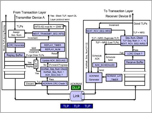
Elements of the ACK/NAK ProtocolFigure 5-3 is a block diagram of a transmitter and a remote receiver connected via a Link. The diagram shows all of the major Data Link Layer elements associated with reliable TLP transfer from the transmitter's Transaction Layer to the receiver's Transaction Layer. Packet order is maintained by the transmitter's and receiver's Transaction Layer. Figure 5-3. Elements of the ACK/NAK Protocol
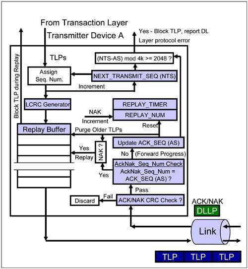
Transmitter Elements of the ACK/NAK ProtocolFigure 5-4 on page 215 illustrates the transmitter Data Link Layer elements associated with processing of outbound TLPs and inbound ACK/NAK DLLPs. Figure 5-4. Transmitter Elements Associated with the ACK/NAK Protocol
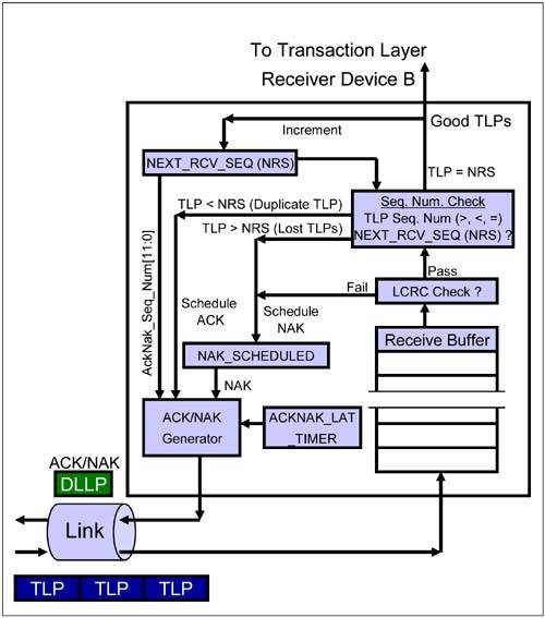
Replay BufferThe replay buffer stores TLPs with all fields including the Data Link Layer-related Sequence Number and LCRC fields. The TLPs are saved in the order of arrival from the Transaction Layer before transmission. Each TLP in the Replay Buffer contains a Sequence Number which is incrementally greater than the sequence number of the previous TLP in the buffer. When the transmitter receives acknowledgement via an ACK DLLP that TLPs have reached the receiver successfully, it purges the associated TLPs from the Replay Buffer. If, on the other hand, the transmitter receives a NAK DLLP, it replays (i.e., re-transmits) the contents of the buffer. NEXT_TRANSMIT_SEQ CounterThis counter generates the Sequence Number assigned to each new transmitted TLP. The counter is a 12-bit counter that is initialized to 0 at reset, or when the Data Link Layer is in the inactive state. It increments until it reaches 4095 and then rolls over to 0 (i.e., it is a modulo 4096 counter). LCRC GeneratorThe LCRC Generator provides a 32-bit LCRC for the TLP. The LCRC is calculated using all fields of the TLP including the Header, Data Payload, ECRC and Sequence Number. The receiver uses the TLP's LCRC field to check for a CRC error in the received TLP. REPLAY_NUM CountThis 2-bit counter stores the number of replay attempts following either reception of a NAK DLLP, or a REPLAY_TIMER time-out. When the REPLAY_NUM count rolls over from 11b to 00b, the Data Link Layer triggers a Physical Layer Link-retrain (see the description of the LTSSM recovery state on page 532). It waits for completion of re-training before attempting to transmit TLPs once again. The REPLAY_NUM counter is initialized to 00b at reset, or when the Data Link Layer is inactive. It is also reset whenever an ACK is received, indicating that forward progress is being made in transmitting TLPs. REPLAY_TIMER CountThe REPLAY_TIMER is used to measure the time from when a TLP is transmitted until an associated ACK or NAK DLLP is received. The REPLAY_TIMER is started (or restarted, if already running) when the last Symbol of any TLP is sent. It restarts from 0 each time that there are outstanding TLPs in the Replay Buffer and an ACK DLLP is received that references a TLP still in the Replay Buffer. It resets to 0 and holds when there are no outstanding TLPs in the Replay Buffer, or until restart conditions are met for each NAK received (except during a replay), or when the REPLAY_TIMER expires. It is not advanced (i.e., its value remains fixed) during Link re-training. ACKD_SEQ CountThis 12-bit register tracks or stores the Sequence Number of the most recently received ACK or NAK DLLP. It is initialized to all 1s at reset, or when the Data Link Layer is inactive. This register is updated with the AckNak_Seq_Num [11:0] field of a received ACK or NAK DLLP. The ACKD_SEQ count is compared with the NEXT_TRANSMIT_SEQ count. IF (NEXT_TRANSMIT_SEQ - ACKD_SEQ) mod 4096 Also, the ACKD_SEQ count is used to check for forward progress made in transmitting TLPs. If no forward progress is made after 3 additional replay attempts, the Link in re-trained. DLLP CRC CheckThis block checks for CRC errors in DLLPs returned from the receiver. Good DLLPs are further processed. If a DLLP CRC error is detected, the DLLP is discarded and an error reported. No further action is taken. Definition: The Data Link Layer is in the inactive state when the Physical Layer reports that the Link is non-operational or nothing is connected to the Port. The Physical Layer is in the non-operational state when the Link Training and Status State Machine (LTSSM) is in the Detect, Polling, Configuration, Disabled, Reset or Loopback states during which LinkUp = 0 (see Chapter 14 on 'Link Initialization and Training'). While in the inactive state, the Data Link Layer state machines are initialized to their default values and the Replay Buffer is cleared. The Data Link Layer exits the inactive state when the Physical Layer reports LinkUp = 1 and the Link Disable bit of the Link Control register = 0. Receiver Elements of the ACK/NAK ProtocolFigure 5-5 on page 218 illustrates the receiver Data Link Layer elements associated with processing of inbound TLPs and outbound ACK/NAK DLLPs. Figure 5-5. Receiver Elements Associated with the ACK/NAK Protocol
Receive BufferThe receive buffer temporarily stores received TLPs while TLP CRC and Sequence Number checks are performed. If there are no errors, the TLP is processed and transferred to the receiver's Transaction Layer. If there are errors associated with the TLP, it is discarded and a NAK DLLP may be scheduled (more on this later in this chapter). If the TLP is a duplicate TLP (more on this later in this chapter), it is discarded and an ACK DLLP is scheduled. If the TLP is a 'nullified' TLP, it is discarded and no further action is taken (see "Switch Cut-Through Mode" on page 248). LCRC Error CheckThis block checks for LCRC errors in the received TLP using the TLP's 32-bit LCRC field. NEXT_RCV_SEQ CountThe 12-bit NEXT_RCV_SEQ counter keeps track of the next expected TLP's Sequence Number. This counter is initialized to 0 at reset, or when the Data Link Layer is inactive. This counter is incremented once for each good TLP received that is forwarded to the Transaction Layer. The counter rolls over to 0 after reaching a value of 4095. The counter is not incremented for TLPs received with CRC error, nullified TLPs, or TLPs with an incorrect Sequence Number. Sequence Number CheckAfter the CRC error check, this block verifies that a received TLP's Sequence Number matches the NEXT_RCV_SEQ count.
NAK_SCHEDULED FlagThe NAK_SCHEDULED flag is set when the receiver schedules a NAK DLLP to return to the remote transmitter. It is cleared when the receiver sees the first TLP associated with the replay of a previously-Nak'd TLP. The specification is unclear about whether the receiver should schedule additional NAK DLLP for bad TLPs received while the NAK_SCHEDULED flag is set. It is the authors' interpretation that the receiver must not schedule the return of additional NAK DLLPs for subsequently received TLPs while the NAK_SCHEDULED flag remains set. ACKNAK_LATENCY_TIMERThe ACKNAK_LATENCY_TIMER monitors the elapsed time since the last ACK or NAK DLLP was scheduled to be returned to the remote transmitter. The receiver uses this timer to ensure that it processes TLPs promptly and returns an ACK or a NAK DLLP when the timer expires or exceeds its set value. The timer value is set based on a formula described in "Receivers ACKNAK_LATENCY_TIMER" on page 237. ACK/NAK DLLP GeneratorThis block generates the ACK or NAK DLLP upon command from the LCRC or Sequence Number check block. The ACK or NAK DLLP contains an AckNak_Seq_Num[11:0] field obtained from the NEXT_RCV_SEQ counter. ACK or NAK DLLPs contain a AckNak_Seq_Num[11:0] value equal to NEXT_RCV_SEQ count - 1.  |

| [ Team LiB ] |
|