| [ Team LiB ] |


|
ACK/NAK Protocol DetailsThis section describes the detailed transmitter and receiver behavior in processing TLPs and ACK/NAK DLLPs. The examples demonstrate flow of TLPs from transmitter to the remote receiver in both the normal non-error case, as well as the error cases. Transmitter Protocol DetailsThis section delves deeper into the ACK/NAK protocol. Consider the transmit side of a device's Data Link Layer shown in Figure 5-4 on page 215. Sequence NumberBefore a transmitter sends TLPs delivered by the Transaction Layer, the Data Link Layer appends a 12-bit Sequence Numbers to each TLP. The Sequence Number is generated by the 12-bit NEXT_TRANSMIT_SEQ counter. The counter is initialized to 0 at reset, or when the Data Link Layer is in the inactive state. It increments after each new TLP is transmitted until it reaches its maximum value of 4095, and then rolls over to 0. For each new TLP sent, the transmitter appends the Sequence Number from the NEXT_TRANSMIT_SEQ counter. Keep in mind that an incremented Sequence Number does not necessarily mean a greater Sequence Number (since the counter rolls over when after it reaches a maximum value of 4095). 32-Bit LCRCThe transmitter also appends a 32-bit LCRC (Link CRC) calculated based on TLP contents which include the Header, Data Payload, ECRC and Sequence Number. Replay (Retry) BufferGeneralBefore a device transmits a TLP, it stores a copy of the TLP in a buffer associated with the Data Link Layer referred to as the Replay Buffer (the specification uses the term Retry Buffer). Each buffer entry stores a complete TLP with all of its fields including the Header (up to 16 bytes), an optional Data Payload (up to 4KB), an optional ECRC (up to four bytes), the Sequence Number (12-bits wide, but occupies two bytes) and the LCRC field (four bytes). The buffer size is unspecified. The buffer should be big enough to store transmitted TLPs that have not yet been acknowledged via ACK DLLPs. When the transmitter receives an ACK DLLP, it purges from the Replay Buffer TLPs with equal to or earlier Sequence Numbers than the Sequence Number received with the ACK DLLPs. When the transmitter receives NAK DLLPs, it purges the Replay Buffer of TLPs with Sequence Numbers that are equal to or earlier than the Sequence Number that arrives with the NAK and replays (re-transmits) TLPs of later Sequence Numbers (the remainder TLPs in the Replay Buffer). This implies that a NAK DLLP inherently acknowledges TLPs with equal to or earlier Sequence Numbers than the AckNak_Seq_Num[11:0] of the NAK DLLP and replays the remainder TLPs in the Replay Buffer. Efficient replay strategies are discussed later. Replay Buffer SizingThe Replay Buffer should be large enough so that, under normal operating conditions, TLP transmissions are not throttled due to a Replay Buffer full condition. To determine what buffer size to implement, one must consider the following:
Transmitter's Response to an ACK DLLPGeneralIf the transmitter receives an ACK DLLP, it has positive confirmation that its transmitted TLP(s) have reached the receiver successfully. The transmitter associates the Sequence Number contained in the ACK DLLP with TLP entries contained in the Replay Buffer. A single ACK DLLP returned by the receiver Device B may be used to acknowledge multiple TLPs. It is not necessary that every TLP transmitted must have a corresponding ACK DLLP returned by the remote receiver. This is done to conserve bandwidth by reducing the ACK DLLP traffic on the bus. The receiver gathers multiple TLPs and then collectively acknowledges them with one ACK DLLP that corresponds to the last received good TLP. In InfiniBand, this is referred to as ACK coalescing. The transmitter's response to reception of an ACK DLLP include:
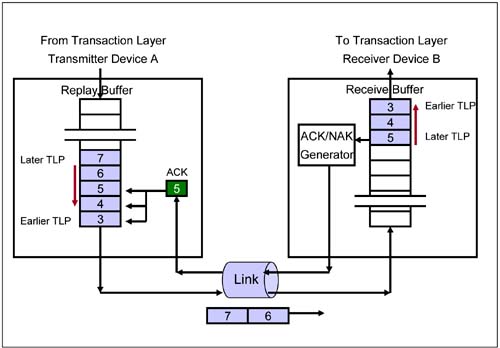
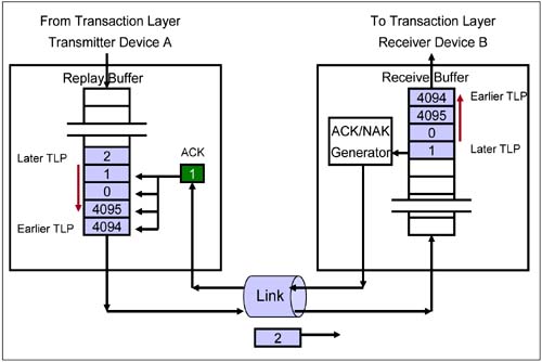
Purging the Replay BufferAn ACK DLLP of a given Sequence Number (contained in the AckNak_Seq_Num[11:0] field) acknowledges the receipt of a TLP with that Sequence Number in the transmitter Replay Buffer, PLUS all TLPs with earlier Sequence Numbers. In other words, an ACK DLLP with a given Sequence Number not only acknowledges a specific TLP in the Replay Buffer (the one with that Sequence Number), but it also acknowledges TLPs of earlier (logically lower) Sequence Numbers. The transmitter purges the Replay Buffer of all TLPs acknowledged by the ACK DLLP. Examples of Transmitter ACK DLLP ProcessingExample 1Consider Figure 5-7 on page 223, with the emphasis on the transmitter Device A.
Figure 5-7. Example 1 that Shows Transmitter Behavior with Receipt of an ACK DLLP
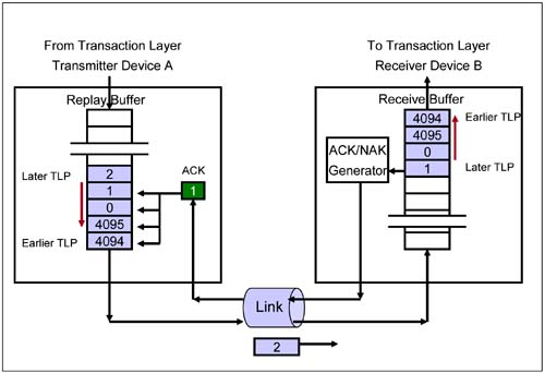
Example 2Consider Figure 5-8, with the emphasis on the transmitter Device A.
Figure 5-8. Example 2 that Shows Transmitter Behavior with Receipt of an ACK DLLP
Transmitter's Response to a NAK DLLPA NAK DLLP received by the transmitter implies that a TLP transmitted at an earlier time was received by the receiver in error. The transmitter first purges from the Replay Buffer any TLP with Sequence Numbers equal to or earlier than the NAK DLLP's AckNak_Seq_Num[11:0]. It then replays (retries) the remainder TLPs starting with the TLP with Sequence Number immediately after the AckNak_Seq_Num[11:0] of the NAK DLLP until the newest TLP. In addition, the transmitter's response to reception of a NAK DLLP include:
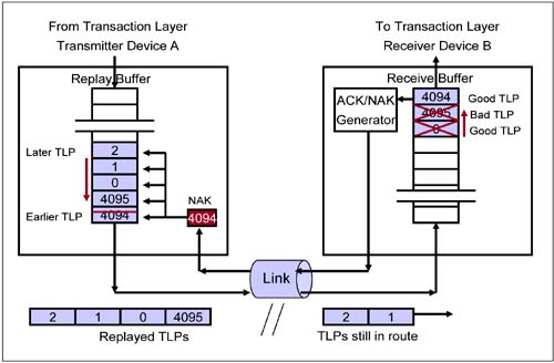
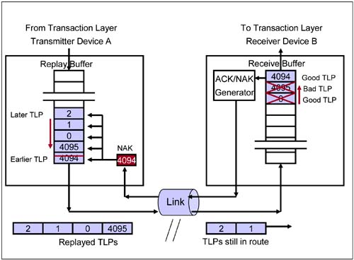
TLP ReplayWhen a Replay becomes necessary, the transmitter blocks the delivery of new TLPs by the Transaction Layer. It then replays (re-sends or retries) the contents of the Replay Buffer starting with the earliest TLP first (of Sequence Number = AckNak_Seq_Num[11:0] + 1) until the remainder of the Replay Buffer is replayed. After the replay event, the Data Link Layer unblocks acceptance of new TLPs from the Transaction Layer. The transmitter continues to save the TLPs just replayed until they are finally acknowledged at a later time. Efficient TLP ReplayACK DLLPs or NAK DLLPs received during replay must be processed. This means that the transmitter must process the DLLPs and, at the very least, store them until the replay is finished. After replay is complete, the transmitter evaluates the ACK or NAK DLLPs and performs the appropriate processing. A more efficient design might begin processing the ACK/NAK DLLPs while the transmitter is still in the act of replaying. By doing so, newly received ACK DLLPs are used to purge the Replay Buffer even while replay is in progress. If another NAK DLLP is received in the meantime, at the very least, the TLPs that were acknowledged have been purged and would not be replayed. During replay, if multiple ACK DLLPs are received, the ACK DLLP received last with the latest Sequence Number can collapse earlier ACK DLLPs of earlier Sequence Numbers. During the replay, the transmitter can concurrently purge TLPs of Sequence Number equal to and earlier than the AckNak_Seq_Num[11:0] of the last received ACK DLLP. Example of Transmitter NAK DLLP ProcessingConsider Figure 5-9 on page 226, with focus on transmitter Device A.
Figure 5-9. Example that Shows Transmitter Behavior on Receipt of a NAK DLLP
Repeated Replay of TLPsEach time the transmitter receives a NAK DLLP, it replays the Replay Buffer contents. The transmitter uses a 2-bit Replay Number counter, referred to as the REPLAY_NUM counter, to keep track of the number of replay events. Reception of a NAK DLLP increments REPLAY_NUM. This counter is initialized to 0 at reset, or when the Data Link Layer is inactive. It is also reset if an ACK or NAK DLLP is received with a later Sequence Number than that contained in the ACKD_SEQ register. As long as forward progress is made in transmitting TLPs the REPLAY_NUM counter resets. When a fourth NAK is received, indicating no forward progress has been made after several tries, the counter rolls over to zero. The transmitter will not replay the TLPs a fourth time but instead it signals a replay number rollover error. The device assumes that the Link is non-functional or that there is a Physical Layer problem at either the transmitter or receiver end. What Happens After the Replay Number Rollover?A transmitter's Data Link Layer triggers the Physical Layer to re-train the Link. The Physical Layer Link Training and Status State Machine (LTSSM) enters the Recovery State (see "Recovery State" on page 532). The Replay Number Rollover error bit is set ("Advanced Correctable Error Handling" on page 384) in the Advanced Error Reporting registers (if implemented). The Replay Buffer contents are preserved and the Data Link Layer is not initialized by the re-training process. Upon Physical Layer re-training exit, assuming that the problem has been cleared, the transmitter resumes the same replay process again. Hopefully, the TLPs can be re-sent successfully on this attempt. The specification does not address a device's handling of repeated re-train attempts. The author recommends that a device track the number of re-train attempts. After a re-train rollover the device could signal a Data Link Layer protocol error indicating the severity as an Uncorrectable Fatal Error. Transmitter's Replay TimerThe transmitter implements a REPLAY_TIMER to measure the time from when a TLP is transmitted until the transmitter receives an associated ACK or NAK DLLP from the remote receiver. A formula (described below) determines the timer's expiration period. Timer expiration triggers a replay event and the REPLAY_NUM count increments. A time-out may arise if an ACK or NAK DLLP is lost en route, or because of an error in the receiver that prevents it from returning an ACK or NAK DLLP. Timer-related rules are:
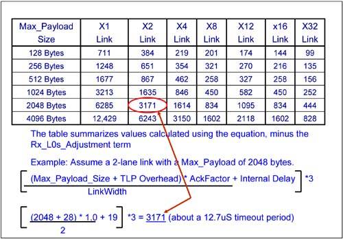
REPLAY_TIMER EquationThe timer is loaded with a value that reflects the worst-case latency for the return of an ACK or NAK DLLP. This time depends on the maximum data payload allowed for a TLP and the width of the Link. The equation to calculate the REPLAY_TIMER value required is:
The value in the timer represents a symbol time (4ns). The equation fields are defined as follows:
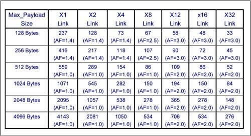
REPLAY_TIMER Summary TableFigure 5-10 on page 229 is a summary table that shows possible timer load values with various variables plugged into the REPLAY_TIMER equation. Transmitter DLLP HandlingThe DLLP CRC Error Checking block determines whether there is a CRC error in the received DLLP. The DLLP includes a 16-bit CRC for this purpose (see Table 5-1 on page 219). If there are no DLLP CRC errors, then the DLLPs are further processed. If a DLLP CRC error is detected, the DLLP is discarded, and the error is reported as a DLLP CRC error to the error handling logic which logs the error in the optional Advanced Error Reporting registers (see Bad DLLP in "Advanced Correctable Error Handling" on page 384). No further action is taken. Discarding an ACK or NAK DLLP received in error is not a severe response because a subsequently received DLLP will accomplish the same goal as the discarded DLLP. The side effect of this action is that associated TLPs are purged a little later than they would have been or that a replay happens at a later time. If a subsequent DLLP is not received in time, the transmitter REPLAY_TIMER expires anyway, and the TLPs are replayed. Receiver Protocol DetailsConsider the receive side of a device's Data Link Layer shown in Figure 5-5 on page 218. TLP Received at Physical LayerTLPs received at the Physical Layer are checked for STP and END framing errors as well as other receiver errors such as disparity errors. If there are no errors, the TLPs are passed to the Data Link Layer. If there are any errors, the TLP is discarded and the allocated storage is freed up. The Data Link Layer is informed of this error so that it can schedule a NAK DLLP. (see "Receiver Schedules a NAK" on page 233). Received TLP Error CheckThe receiver accepts TLPs from the Link into a receiver buffer and checks for CRC errors. The receiver calculates an expected LCRC value based on the received TLP (excluding the LCRC field) and compares this value with the TLP's 32-bit LCRC. If the two match, the TLP is good. If the two LCRC values do not match, the received TLP is bad and the receiver schedules a NAK DLLP to be returned to the remote transmitter. The receiver also checks for other types of non-CRC related errors (such as that described in the next section). Next Received TLP's Sequence NumberThe receiver keeps track of the next expected TLP's Sequence Number via a 12-bit counter referred to as the NEXT_RCV_SEQ counter. This counter is initialized to 0 at reset, or when the Data Link Layer is inactive. This counter is incremented once for each good TLP that is received and forwarded to the Transaction Layer. The counter rolls over to 0 after reaching a value of 4095. The receiver uses the NEXT_RCV_SEQ counter to identify the Sequence Number that should be in the next received TLP. If a received TLP has no LCRC error, the device compares its Sequence Number with the NEXT_RCV_SEQ count. Under normal operational conditions, these two numbers should match. If this is the case, the receiver accepts the TLP, forwards the TLP to the Transaction Layer, increments the NEXT_RCV_SEQ counter and is ready for the next TLP. An ACK DLLP may be scheduled for return if the ACKNAK_LATENCY_ TIMER expires or exceeds its set value. The receiver is ready to perform a comparison on the next received TLP's Sequence Number. In some cases, a received TLP's Sequence Number may not match the NEXT_RCV_SEQ count. The received TLP's Sequence Number may be either logically greater than or logically less than NEXT_RCV_SEQ count (a logical number in this case accounts for the count rollover, so in fact a logically greater number may actually be a lower number if the count rolls over). See "Receiver Sequence Number Check" on page 234 for details on these two abnormal conditions. For a TLP received with a CRC error, or a nullified TLP or a TLP for which the Sequence Number check described above fails, the NEXT_RCV_SEQ counter is not incremented. Receiver Schedules An ACK DLLPIf the receiver does not detect an LCRC error (see "Received TLP Error Check" on page 230) or a Sequence Number related error (see "Next Received TLP's Sequence Number" on page 230) associated with a received TLP, it accepts the TLP and sends it to the Transaction Layer. The NEXT_RCV_SEQ counter is incremented and the receiver is ready for the next TLP. At this point, the receiver can schedule an ACK DLLP with the Sequence Number of the received TLP (see the AckNak_Seq_Num[11:0] field described in Table 5-1 on page 219). Alternatively, the receiver could also wait for additional TLPs and schedule an ACK DLLP with the Sequence Number of the last good TLP received. The receiver is allowed to accumulate a number of good TLPs and then sends one aggregate ACK DLLP with a Sequence Number of the latest good TLP received. The coalesced ACK DLLP acknowledges the good receipt of a collection of TLPs starting with the oldest TLP in the transmitter's Replay Buffer and ending with the TLP being acknowledged by the current ACK DLLP. By doing so, the receiver optimizes the use of Link bandwidth due to reduced ACK DLLP traffic. The frequency with which ACK DLLPs are scheduled for return is described in "Receivers ACKNAK_LATENCY_TIMER" on page 237. When the ACKNAK_LATENCY_ TIMER expires or exceeds its set value and TLPs are received, an ACK DLLP with a Sequence Number of the last good TLP is returned to the transmitter. When the receiver schedules an ACK DLLP to be returned to the remote transmitter, the receiver might have other packets (TLPs, DLLPs or PLPs) enqueued that also have to be transmitted on the Link in the same direction as the ACK DLLP. This implies that the receiver may not immediately return the ACK DLLP to the transmitter, especially if a large TLP (with up to a 4KB data payload) is already being transmitted (see "Recommended Priority To Schedule Packets" on page 244). The receiver continues to receive TLPs and as long as there are no detected errors (LCRC or Sequence Number errors), it forwards the TLPs to the Transaction Layer. When the receiver has the opportunity to return the ACK DLLP to the remote transmitter, it appends the Sequence Number of the latest good TLP received and returns the ACK DLLP. Upon receipt of the ACK DLLP, the remote transmitter purges its Replay Buffer of the TLPs with matching Sequence Numbers and all TLPs transmitted earlier than the acknowledged TLP. Example of Receiver ACK SchedulingExample: Consider Figure 5-11 on page 233, with focus on the receiver Device B.
Figure 5-11. Example that Shows Receiver Behavior with Receipt of Good TLP
NAK Scheduled FlagThe receiver implements a Flag bit referred to as the NAK_SCHEDULED flag. When a receiver detects a TLP CRC error, or any other non-CRC related error that requires it to schedule a NAK DLLP to be returned, the receiver sets the NAK_SCHEDULED flag and clears it when the receiver detects replayed TLPs from the transmitter for which there are no CRC errors. Receiver Schedules a NAKUpon receipt of a TLP, the first type of error condition the receiver may detect is a TLP LCRC error (see "Received TLP Error Check" on page 230). The receiver discards the bad TLP. If the NAK_SCHEDULED flag is clear, it schedules a NAK DLLP to return to the transmitter. The NAK_SCHEDULED flag is then set. The receiver uses the NEXT_RCV_SEQ count - 1 count value as the AckNak_Seq_Num [11:0] field in the NAK DLLP (Table 5-1 on page 219). At the time the receiver schedules a NAK DLLP to return to the transmitter, the Link may be in use to transmit other queued TLPs, DLLPs or PLPs. In that case, the receiver delays the transmission of the NAK DLLP (see "Recommended Priority To Schedule Packets" on page 244). When the Link becomes available, however, it sends the NAK DLLP to the remote transmitter. The transmitter replays the TLPs from the Replay Buffer (see "TLP Replay" on page 225). In the meantime, TLPs currently en route continue to arrive at the receiver. These TLPs have later Sequence Numbers than the NEXT_RCV_SEQ count. The receiver discards them. The specification is unclear about whether the receiver should schedule a NAK DLLP for these TLPs. It is the authors' interpretation that the receiver must not schedule the return of additional NAK DLLPs for subsequently received TLPs while the NAK_SCHEDULED flag remains set. The receiver detects a replayed TLP when it receives a TLP with Sequence Numbers that matches NEXT_RCV_SEQ count. If the replayed TLPs arrive with no errors, the receiver increments NEXT_RCV_SEQ count and clears the NAK_SCHEDULED flag. The receiver may schedule an ACK DLLP for return to the transmitter if the ACKNAK_LATENCY_TIMER expires. The good replayed TLPs are forwarded to the Transaction Layer. There is a second scenario under which the receiver schedules NAK DLLPs to return to the transmitter. If the receiver detects a TLP with a later Sequence Number than the next expected Sequence Number indicated by NEXT_RCV_SEQ count or for which the TLP has a Sequence Number that is separated from NEXT_RCV_SEQ count by more than 2048, the above described procedure is repeated. See "Receiver Sequence Number Check" below for the reasons why this could happen. The two error conditions just described wherein a NAK DLLP is scheduled for return are reported as errors associated with the Data Link Layer. The error reported is a bad TLP error with a severity of correctable. Receiver Sequence Number CheckEvery received TLP that passes the CRC check goes through a Sequence Number check. The received TLPs Sequence Number is compared with the NEXT_RCV_SEQ count. Below are three possibilities:
Receiver Preserves TLP OrderingIn addition to guaranteeing reliable TLP transport, the ACK/NAK protocol preserves packet ordering. The receiver's Transaction Layer receives TLPs in the same order that the transmitter sent them. A transmitter correctly orders TLPs according to the ordering rules before transmission in order to maintain correct program flow and to eliminate the occurrence of potential deadlock and livelock conditions (see Chapter 8, entitled "Transaction Ordering," on page 315). The Receiver is required to preserve TLP order (otherwise, application program flow is altered). To preserved this order, the receiver applies three rules:
For TLPs that arrive after the first bad TLP, the motivation to discard these TLPs, not forward them to the Transaction Layer and schedule a NAK DLLP is as follows. When the receiver detects a bad TLP, it discards it and any new TLPs in the pipeline. The receiver then waits for TLP replay. After verifying that there are no errors in the replayed TLP(s), the receiver forwards them to the Transaction Layer and resumes acceptance of new TLPs in the pipeline. Doing so preserves TLP receive and acceptance order at the receivers Transaction Layer. Example of Receiver NAK SchedulingExample: Consider Figure 5-12 on page 237 with emphasis on the receiver Device B.
Figure 5-12. Example that Shows Receiver Behavior When It Receives Bad TLPs
Receivers ACKNAK_LATENCY_TIMERThe ACKNAK_LATENCY_TIMER measures the duration since an ACK or NAK DLLP was scheduled for return to the remote transmitter. This timer has a value that is approximately 1/3 that of the transmitter REPLAY_TIMER. When the timer expires, the receiver schedules an ACK DLLP with a Sequence Number of the last good unacknowledged TLP received. The timer guarantees that the receiver schedules an ACK or NAK DLLP for a received TLP before the transmitter's REPLAY_TIMER expires causing it to replay. The timer resets to 0 and restarts when an ACK or NAK DLLP is scheduled. The timer resets to 0 and holds when:
ACKNAK_LATENCY_TIMER EquationThe receiver's ACKNAK_ LATENCY_TIMER is loaded with a value that reflects the worst-case transmission latency in sending an ACK or NAK in response to a received TLP. This time depends on the anticipated maximum payload size and the width of the Link. The equation to calculate the ACKNAK_LATENCY_TIMER value required is:
The value in the timer represents symbol times (a symbol time = 4 ns). The fields above are defined as follows:
It turns out that the entries in this table are approximately a third in value of the REPLAY_TIMER latency values in Figure 5-10 on page 229. ACKNAK_LATENCY_TIMER Summary TableFigure 5-13 on page 239 is a summary table that shows possible timer load values with various variables plugged into the ACKNAK_LATENCY_TIMER equation. Figure 5-13. Table to Calculate ACKNAK_LATENCY_TIMER Load Value
|


| [ Team LiB ] |
|