| [ Team LiB ] |


|
Two Categories of System ResetThe PCI Express specification describes two reset generation mechanisms. The first mechanism is a system generated reset referred to as Fundamental Reset. The second mechanism is an In-band Reset (communicated downstream via the Link from one device to another) referred to as the Hot Reset. Fundamental ResetFundamental Reset causes a device's state machines, hardware logic, port states and configuration registers (except sticky registers of a device that can draw valid Vaux) to initialize to their default conditions. There are two types of Fundamental Reset:
When Fundamental Reset is asserted:
After Fundamental Reset Exit:
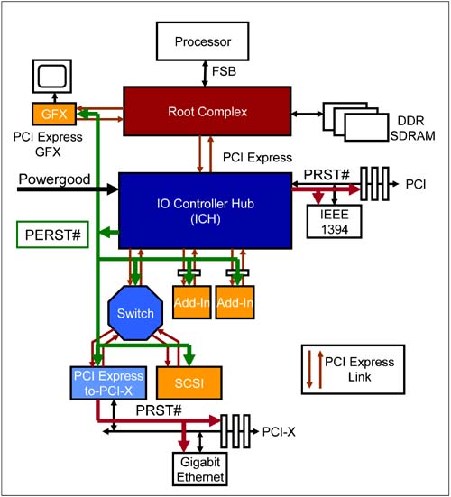
Methods of Signaling Fundamental ResetFundamental Reset may be signaled via an auxiliary side-band signal called PERST# (PCI Express Reset, asserted low). When PERST# is not provided to an add-in card or component, Fundamental Reset is generated autonomously by the component or add-in card. Below is a description of the two mechanisms of Fundamental Reset generation. PERST# Type Fundamental Reset GenerationA central resource device, e.g. a chipset, in the PCI Express system provides this source of reset. For example, the IO Controller Hub (ICH) chip in Figure 13-1 on page 490 may generate PERST#. The system power supply (not shown in figure) generates a 'POWERGOOD' signal once main power is turned on and stable. The ICH Reset logic in-turn uses this signal to assert PERST# when POWERGOOD (asserted High) is deasserted. If power is cycled, POWERGOOD toggles and causes PERST# to assert and deassert. This is the Cold Reset. If the system provides a method of toggling POWERGOOD without cycling through power (as via a button on the chassis) then also PERST# asserts and deasserts. This is the Warm Reset. Figure 13-1. PERST# Generation
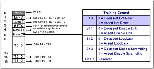
The PERST# signal feeds all PCI Express devices on the motherboard including the connectors and graphics controller. Devices may choose to use PERST# but are not required to use it as the source of reset. The PERST# signal also feeds the PCI Express-to-PCI-X bridge shown in the figure. The bridge forwards this reset to the PCI-X bus as PCI-X bus RST#. ICH also generates PRST# for the PCI bus. Autonomous Method of Fundamental Reset GenerationA device can be designed to generate its own Fundamental Reset upon detection of application (or re-application) of main power. The specification does not describe the mechanism for doing so. The self reset generation mechanism can be built into the device or may be designed as external logic, for example, on a add-in card that detects Power-On and generates a local reset to the device. The device must also generate an autonomous Fundamental Reset if it detects its power go outside of the limits specified. A device should support the autonomous method of triggering a Fundamental Reset given that the specification is not clear about requirement of system PERST# support. In-Band Reset or Hot ResetHot Reset is propagated in-band via the transmission of TS1 Ordered-Sets (shown in Figure 13-2) with bit 0 of symbol 5 in the TS1 Ordered-Set asserted. The TS1 Ordered-Set is transmitted on all Lanes with the correct Link # and Lane# symbols. These TS1 Ordered-Sets are continuously transmitted for 2 ms. Both transmitter and receiver of Hot Reset end up in the detect state (see "Hot Reset State" on page 544). Hot Reset, in general, is a software generated reset. Figure 13-2. TS1 Ordered-Set Showing the Hot Reset Bit
Hot Reset is propagated downstream. Hot Reset is not propagated upstream. This means that only the Root Complex and Switches are able to generate Hot Reset. Endpoints do not generate Hot Reset. A switch that receives a Hot Reset TS1 Ordered-Set on its upstream port must pass it to all its downstream ports. In addition, the switch resets itself. All devices downstream of a switch that receive the Hot Reset TS1 Ordered-Set will reset themselves. Response to Receiving a Hot Reset CommandWhen a device receives a Hot Reset command:
Switches Generate Hot Reset on Their Downstream PortsThe following are a list of bullets that indicate when a switch generates a Hot Reset on ALL its downstream ports:
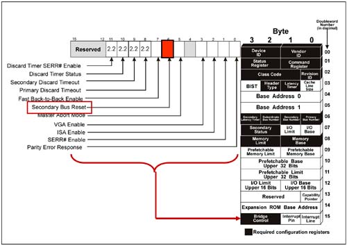
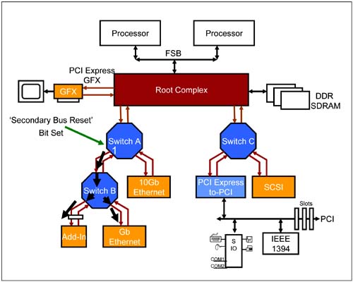
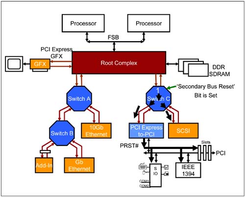
Bridges Forward Hot Reset to the Secondary BusIf a bridge such as a PCI Express-to-PCI(-X) bridge detects a Hot Reset on its upstream port, it must assert the PRST# signal on its secondary PCI(-X) bus. How Does Software Tell a Device (e.g. Switch or Root Complex) to Generate Hot Reset?Software tells a root complex or switch to generate a Hot Reset on a specific port by writing a 1 followed by 0 to the 'Secondary Bus Reset' bit in the Bridge Control register of that associated port's configuration header. See Figure 13-3 on page 493 for the location of this bit. Consider the example shown in Figure 13-4 on page 494. Software writes a 1 to the 'Secondary Bus Reset' register of Switch A's downstream left side port. Switch A generates a Hot Reset on that port by forwarding TS1 Ordered-Sets with the Hot Reset bit set. Switch A does not generate a Hot Reset on its right side port. Switch B receives this Hot Reset on its upstream port and forwards it on all downstream ports to the two endpoints. Figure 13-3. Secondary Bus Reset Register to Generate Hot Reset
Figure 13-4. Switch Generates Hot Reset on One Downstream Port
If software writes to the 'Secondary Bus Reset' bit of the switch's upstream port, then the switch generates a Hot Reset on ALL its downstream ports. Consider the example shown in Figure 13-5 on page 495. Software writes a 1 to the 'Secondary Bus Reset' register of Switch C's upstream port. Switch C generates a Hot Reset on ALL downstream ports by forwarding TS1 Ordered-Sets with the Hot Reset bit set on both ports. The PCI Express-to-PCI bridge receives this Hot Reset and forwards it on to the PCI bus by asserting PRST#. Figure 13-5. Switch Generates Hot Reset on All Downstream Ports
A device is in the L0 state when the 'Secondary Bus Reset' bit is set. The device (upstream device) then goes through the Recovery state of the LTSSM (see "Recovery State" on page 532) before it generates the TS1 Ordered-Sets with the Hot Reset bit set and then enters the Hot Reset state (see "Hot Reset State" on page 544). The Hot Reset TS1 Ordered-Sets are generated continuously for 2 ms and then the device exits to the Detect state where it is ready to start the Link training and initialization process. The receiver (downstream device) of the Hot Reset TS1 Ordered-Sets will enter the Hot Reset state through the Recovery state. It exits to the Detect state if it receives at least two Hot Reset TS1 Ordered-Sets. Both upstream and downstream devices are initialized and end up in the Detect state from which they are ready to being Link training and initialization. If the downstream device is a switch or bridge, it passes on the Hot Reset to its downstream ports or bus. |
| [ Team LiB ] |
|