Link Initialization and Training Overview
General
Link initialization and training is a Physical Layer control process that configures and initializes a device's Physical Layer, port, and associated Link so that normal packet traffic can proceed on the Link. This process is automatically initiated after reset without any software involvement. A sub-set of the Link training and initialization process, referred to as Link re-training, is initiated automatically as a result of a wakeup event from a low power mode, or due to an error condition that renders the Link inoperable. The Link Training and Status State Machine (LTSSM) is the Physical Layer sub-block responsible for the Link training and initialization process (see Figure 14-1).X
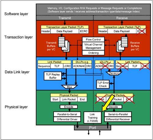
A receiver may optionally check for violations of the Link training and initialization protocol. If such an error occurs, it may be reported as a 'Link Training Error' to the error reporting logic (see "Link Errors" on page 379).
The following are configured during the Link training and initialization process:
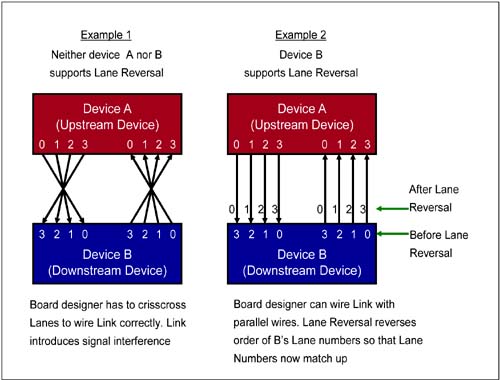
Link Width is established and set. Two devices with a different number of port Lanes may be connected. For example, one device with a x2 port may be connected to a device with a x4 port. During Link training and initialization, the Physical Layer of both devices determines and sets the Link width to the minimum Lane width of the two (i.e., x2). Other Link negotiated behaviors include Lane reversal, splitting of ports into multiple Links, and the configuration of a cross-Link. Lane Reversal on a multi-Lane device's port (if reversal is required). The Lanes on a device's port are numbered by design. When wiring up a Link to connect two devices, a board designer should match up the lane numbers of each device's port so that Lane 0 of one device's port connects to Lane 0 of the remote device's port, Lane n to Lane n of the remote device's port, and so on. Due to the way the Lanes are organized on the pins of the device's package, it may not be possible to match up the Lanes of the two devices without crisscrossing the wires (see Figure 14-2 on page 502). Crisscrossed wires will introduce interference into the Link. If however, one or both of the devices support Lane Reversal, the designer could wire the Lanes in parallel fashion. During the Link training and initialization process, one device reverses the Lane numbering so the Lane numbers of the two ports would match up (Figure 14-2 on page 502). Unfortunately, the specification does not require devices to support the Lane Reversal feature. Hence, the designer must verify that at least one of the two devices connected via a Link supports this feature before wiring the Lanes of the two ports in reverse order. If the device supports this feature, the Lane Reversal process may permit a multi-Lane Link to be split into multiple Links that connect to multiple devices. More on this feature later.
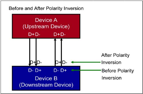
Polarity Inversion may be necessary. The D+ and D- differential pair terminals for two devices may not be connected correctly, or may be intentionally reversed so that the signals do not crisscross when wiring the Link. If Lanes are wired with D+ and D- of one device wired to D- and D+ of the remote device, respectively, the Polarity Inversion feature reverses the D+ and D- signal polarities of the receiver differential terminal. Figure 14-3 illustrates the benefit of this feature on a x1 Link. Support for Polarity Inversion is mandatory.
Link Data Rate.
Link initialization and training is completed at the default 2.5Gbit/s Generation 1 data rate. In the future, Generation 2 PCI Express will support higher data rates of 5Gbit/s and 10Gbit/s. During training, each node advertises its highest data rate capability. The Link is then initialized with the highest common frequency that both neighbors can support.
Bit Lock.
Before Link training begins, the receiver PLL is not yet sync'd with the remote transmitter's transmit clock, and the receiver is unable to differentiate between one received bit and another. During Link training, the receiver PLL is sync'd to the transmit clock and the receiver is then able to shift in the received serial bit stream. See "Achieving Bit Lock" on page 440.
Symbol Lock.
Before training, the receiver has no way of discerning the boundary between two, 10-bit sympols. During training, when TS1 and TS2 Ordered-Sets are exchanged, the receiver is able to locate the COM symbol (using its unique encoding) and uses it to initialize the deserializer. See "Symbol Boundary Sensing (Symbol Lock)" on page 441.
Lane-to-Lane De-skew.
Due to Link wire length variations and the different driver/receiver characteristics on a multi-Lane Link, each of the parallel bit streams that represent a packet are transmitted simultaneously, but they do not arrive at the receivers on each lane at the same time. The receiver circuit must compensate for this skew by adding or removing delays on each Lane so that the receiver can receive and align the serial bit streams of the packet (see "Lane-to-Lane De-Skew" on page 444). This deskew feature combined with the Polarity Inversion and Lane Reversal features, greatly simplifies the designer's task of wiring up the high speed Link.
 |

