Ordered-Sets Used During Link Training and Initialization
Physical Layer Packets (PLPs), referred to as Ordered-Sets, are exchanged between neighboring devices during the Link training and initialization process. These packets were briefly described in the section on "Ordered-Sets" on page 433. The five Ordered-Sets are:
Training Sequence 1 and 2 (TS1 and TS2), Electrical Idle, Fast Training Sequence (FTS), and Skip (SKIP) Ordered-Sets.
Their character structure is summarized in Figure 14-4 on page 504.
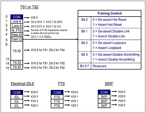
TS1 and TS2 Ordered-Sets
The TS1 and TS2 Ordered-Sets are each comprised up of 16 symbols. Structurally, there is not much difference between a TS1 and TS2 Ordered-Set, other than the TS Identifier (symbols 6-15) which contains a D10.2 for TS1 and D5.2 for the TS2 Ordered-Set. They are exchanged during the Polling, Configuration and Recovery states of the LTSSM described in "Link Training and Status State Machine (LTSSM)" on page 508. The TS1 and TS2 symbols consist of:
Symbol 0 (COM):
The K28.5 character identifies the start of an Ordered-Set. The receiver uses this character to achieve Bit Lock and Symbol Lock as described in "Achieving Bit Lock" on page 440 and "Symbol Boundary Sensing (Symbol Lock)" on page 441. By locating this character on a synchronized transmission of TS1 or TS2 Ordered-Sets on a multi-Lane Link, the receiver can de-skew the Lanes.
Symbol 1 (Link #):
In the early stages of Link training, when the TS1 and TS2 Ordered-Sets are exchanged, this field contains the PAD symbol (transmitted as a null symbol). During the configuration state of the LTSSM, this field contains an assumed Link Number. TS1 and TS2 Ordered-Sets driven from different ports of a switch contain different Link Numbers.
Symbol 2 (Lane #):
In the early stages of Link training when the TS1 and TS2 Ordered-Sets are exchanged, this field contains the PAD symbol (transmitted as a null symbol). During the configuration state of the LTSSM, this field contains an assumed Lane Number for each Lane of a Link. The TS1 and TS2 Ordered-Sets driven on each Lane of a given link contain different numbers.
Symbol 3 (N_FTS):
Contains the number of Fast Training Sequences. The exchange of FTS Ordered-Sets is used to achieve Bit Lock and Symbol Lock when exiting from the L0s to the L0 power state. During Link training at Link initialization, when TS1 or TS2 Ordered-Sets are exchanged, the receiver sends the remote transmitter the N_FTS field to indicate how many FTS Ordered-Sets it must receive to reliably obtain Bit and Symbol Lock. Armed with this information, the transmitter sends at least that many FTS Ordered-Sets during exit from the L0s state. A typical value is between two and four. This implies that the transmitter must send at least that many FTS Ordered-Sets during exit from the L0s state. For example, N_FTS = 4 translates to 4 FTS Ordered-Sets = 4 x 4 symbols = 16 x 4ns/symbol = 64ns, the period of time it takes the receiver's PLL to achieve Bit and Symbol Lock during exit from the L0s state. When the Extended Synch bit is set in the transmitter device, 4096 FTS Ordered-Sets must be sent in order to provide external Link monitoring tools with enough time to achieve Bit and Symbol Lock synchronization. During the FTS Ordered set exchange, if the N_FTS period of time expires and the Receiver has not yet obtained Bit Lock, Symbol Lock, and Lane-to-Lane de-skew on all Lanes of the configured Link, the Receiver must transition to the Recovery state of the LTSSM.
Symbol 4 (Rate ID):
Each device informs its neighbor what data transfer rate it supports. A value of D2.0 indicates a 2.5Gbits/s transfer rate, while other values are currently reserved.
Symbol 5 (Training Control):
A device that sends TS1 and TS2 Ordered-Sets uses this symbol to communicate additional information such as: - Bit 0, when set, indicates Hot Reset. - Bit 1, when set, indicates Link Disable. - Bit 2, when set, indicates Enable Loopback. - Bit 3, when set, indicates disable scrambling. - The remainder of the bits are reserved.
Only one bit can be set in this field per Ordered-Set.
Symbol 6-15 (Training Sequence ID):
Driven with D10.2 for TS1 Ordered-Sets and D5.2 for TS2 Ordered-Sets.
See Table 14-1 for a summary of this information.
Table 14-1. Summary of TS1 and TS2 Ordered-Set Contents|
0 | Comma | K28.5 | This is the COM (Comma) symbol. | 1 | 0-255 | D0.0 - D31.7, K23.7 (PAD) | Link Number.
Uses the PAD symbol when there is no Link Number to communicate. | 2 | 0-31 | D0.0 - D31.0, K23.7 (PAD) | Lane Number.
Use the PAD symbol when no there is no Lane Number to communicate. | 3 | 0-255 | D0.0 - D31.7 | N_FTS.
This is the number of FTS Ordered-Sets required by receiver to obtain Bit and Symbol Lock during exit from the L0s state. | 4 | 2 | D2.0 | Data Rate Identifier:
| 5 | Bit 0 = 0,1
Bit 1 = 0,1
Bit 2 = 0,1
Bit 3 = 0,1
Bit 4:7 = 0 | D0.0, D1.0, D2.0, D4.0, D8.0 | Training Control. 0=De-assert, 1 = Assert:
| 6-15 | | D10.2 for TS1 ID
D5.2 for TS2 ID | TS1/TS2 Ordered-Set Identifier. |
Electrical Idle Ordered-Set
The Electrical Idle Ordered-Set consists of four symbols, starting with the COM symbol and followed by three IDL symbols. This Ordered-Set is transmitted to a receiver prior to the transmitter placing its transmit half of the Link in the Electrical Idle state. The receiver detects this Ordered-Set, de-gates its error detection logic and prepares for the Link to go to the Electrical Idle state. Shortly after transmitting the Electrical Idle Ordered-Set, the transmitter drives a differential voltage of less than 20mV peak. For more details on Electrical Idle Ordered-Set usage and the Electrical Idle Link state, see "Electrical Idle" on page 464.
FTS Ordered-Set
The FTS Ordered-Set consists of four symbols, starting with the COM symbol and followed by three FTS symbols. A transmitter that wishes to transition the state of its Link from the L0s low power state (Electrical Idle) to the L0 state sends a defined number of FTS Ordered-Sets to the receiver. The minimum number of FTS Ordered-Sets that the transmitter must send to the receiver is sent to the transmitter by the receiver during Link training and initialization. See "TS1 and TS2 Ordered-Sets" on page 505, Symbol 3.
SKIP Ordered-Set
The Skip Ordered-Set consists of four symbols, starting with the COM symbol and followed by three SKP symbols. It is transmitted at regular intervals from the transmitter to the receiver and is used for Clock Tolerance Compensation as described in "Inserting Clock Compensation Zones" on page 436 and "Receiver Clock Compensation Logic" on page 442.
 |

