Example PCI-Compatible Configuration Access
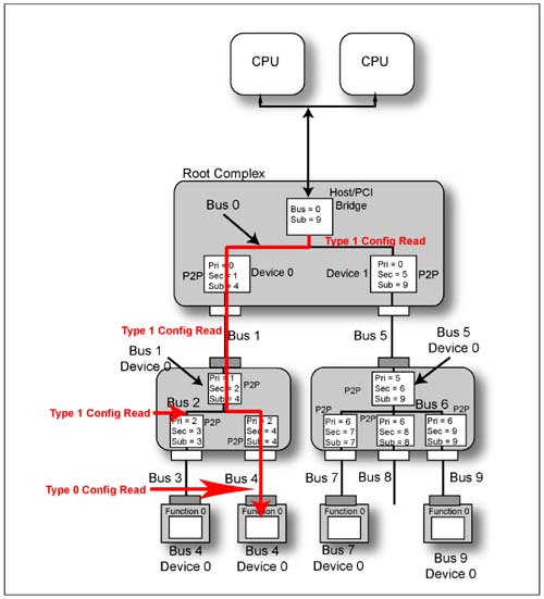
Refer to Figure 20-9 on page 737. The following x86 code sample will cause the Root Complex to perform a read from Bus 4, Device 0, Function 0's Vendor ID configuration register:
mov   dx,0CF8     ;set dx = config address port address
mov   eax,80040000;enable=1, bus 4, dev 0, Func 0, DW 0
out   dx,eax      ;set up address port
mov   dx,0CFC     ; set dx = config data port address
in    ax,dx       ;2 byte read from config data port
On execution of the out (IO Write) instruction, the processor generates an IO write transaction on its FSB targeting the Configuration Address Port in the Root Complex Host/PCI bridge. The data sourced from the eax register is latched into the Configuration Address Port (see Figure 20-2 on page 726). The Host/PCI bridge compares the target bus number (4) specified in the Configuration Address Port to the range of buses (0-through-10) that reside downstream of the bridge. The target bus falls within the range, so the bridge is primed. On execution of the in (IO Read) instruction, the processor generates an IO read transaction on its FSB targeting the Configuration Data Port in the Root Complex Host/PCI bridge. It's a 2-byte read from the first two locations in the Configuration Data Port. Since the target bus is not bus 0, the Host/PCI bridge initiates a Type 1 Configuration read on bus 0. All of the devices on bus 0 latch the transaction request and determine that it is a type 1 Configuration Read request. As a result, both of the virtual PCI-to-PCI bridges in the Root Complex compare the target bus number in the Type 1 request to the range of buses that reside downstream of each of them. The destination bus (4) is within the range of buses downstream of the left-hand bridge, so it passes the packet through to its secondary bus (bus 1). It is passed through as a Type 1 request because this is not the destination bus. The upstream port on the left-hand switch receives the packet and delivers it to the upstream PCI-to-PCI bridge. The bridge determines that the destination bus resides beneath it, so it passes the packet through to bus 2 as a Type 1 request. Both of the bridge's within the switch receive the Type 1 request packet and the right-hand bridge determines that the destination bus is directly beneath it. The bridge passes the Type 1 request packet through to bus 4, but converts into a Type 0 Configuration Read request (because the packet has arrived at the destination bus. Device 0 on bus 4 receives the packet and decodes the target device number. Device 0 decodes the target function number. Function 0 in Device 0 uses the concatenated Extended Register Number and Register Number fields to select the target dword (dword 0; see Figure 20-1 on page 723) in the function's configuration space. The first two Byte Enables in the First Dword Byte Enable field are asserted, so the function returns its Vendor ID in the resulting Completion packet. The Completion packet is routed back to the Host/PCI bridge using the Requester ID field obtained from the Type 0 request packet. The two bytes of read data are delivered to the processor over its FSB, thereby completing the execution of the in instruction. The Vendor ID is placed in the processor's ax register.
 |

