Link Training and Status State Machine (LTSSM)
General
Figure 14-5 on page 510 illustrates the top-level states of the Link Training and Status State Machine (LTSSM). Each state consists of substates that, taken together, comprise that state. The first LTSSM state entered after exiting Fundamental Reset (Cold or Warm Reset) or Hot Reset is the Detect state.
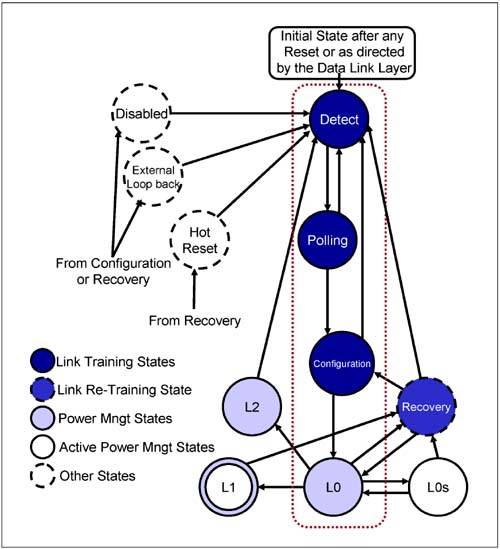
The LTSSM consists of 11 top-level states: Detect, Polling, Configuration, Recovery, L0, L0s, L1, L2, Hot Reset, Loopback, and Disable. These states can be grouped into five categories:
The Link Training states. A Link Re-Training State. The Power Management states. The Active Power Management states, and Other states.
Upon any type of Reset exit, the flow of the LTSSM is through the following Link Training states:
Detect => Polling => Configuration => L0
If a Link error occurs while in the L0 state and it renders the Link inoperable, the LTSSM transitions to the Link Re-Training state (the Recovery state). In this state, the Link is retrained and returned to normal operation (i.e., the L0 state). A Link that is placed in a low power state (such as L1 or L2), returns to the L0 state via the Recovery state.
Without any high-level software involvement, if there are no packets transmitted on the Link (i.e., if the Logical Idle Sequence is transmitted) and a time-out occurs, the device may place its Link into a low power state such as L0s or L1. These are the Active Power Management states.
Power management software may place a device into one of the lower device power states such as D1, D2, D3Hot or D3Cold. Doing so causes the Link to transition from L0 to one of the lower Power Management states such as L1 or L2.
While in the Configuration or the Recovery state, a Link can be directed to enter the Disable state or the Loopback state. While in the Recovery state, a device that receives the Electrical Idle Ordered-Set transits through the Hot Reset state before going to the Detect state. The three states—Disable, Loopback, and Hot Reset—are part of the Other states group.
Overview of LTSSM States
Below is a brief description of the 11 LTSSM states:
Detect:
This is the initial state after reset. While the spec states that the LTSSM may also enter the Detect state as directed by the Data Link Layer, it does not indicate under what circumstances this would occur. In this state, a device detects the presence or absence of a device connected at the far end of the Link. The Detect state may also be entered from a number of other LTSSM states as described later in this chapter.
Polling:
The following conditions are established during the Polling state: - Bit Lock. - Symbol Lock. - Lane Polarity. - Lane Data Rate. - Compliance testing also occurs in this state. During compliance testing, the transmitter outputs a specified compliance pattern. This is intended to be used with test equipment to verify that all of the voltage, noise emission and timing specifications are within tolerance. During the Polling state, a device transmits TS1 and TS2 Ordered-Sets and responds to received TS1 and TS2 Ordered-Sets. Higher bit rate support is advertised via the exchange of TS1 and TS2 Ordered-Sets with the Rate ID field = the highest supported rate.
Configuration:
The following conditions are established during the Configuration state: - Link width. - Link Number. - Lane reversal. - Polarity inversion (if necessary). - Lane-to-Lane de-skew is performed. Both transmitter and receiver are communicating at the negotiated data rate (as of 6/16/03, the generation 1 data rate of 2.5Gb/s). During this state, scrambling can be disabled, the Disable and Loopback states can be entered, and the number of FTS Ordered-Sets required to transition from the L0s state to the L0 state is established.
L0:
This is the normal, fully active state of a Link during which TLPs, DLLPs and PLPs can be transmitted and received.
Recovery:
This state is entered from the L0 state due to an error that renders the Link inoperable. Recovery is also entered from the L1 state when the Link needs re-training before it transitions to the L0 state. In Recovery, Bit Lock and Symbol Lock are re-established in a manner similar to that used in the Polling state. However, the time to transition through this state is much shorter than having to go through the Polling state and then transitioning to the L0 state. Lane-to-Lane de-skew is performed. The number of FTS Ordered-Sets required to transition from the L0s state to the L0 state is re-established.
L0s:
This is a low power, Active Power Management state. It takes a very short time (in the order of 50ns) to transit from the L0s state back to the L0 state (because the LTSSM does not have to go through the Recovery state). This state is entered after a transmitter sends and the remote receiver receives Electrical Idle Ordered-Sets while in the L0 state. Exit from the L0s state to the L0 state involves sending and receiving FTS Ordered-Sets. When transitioning from L0s exit to L0, Lane-to-Lane de-skew must be performed, and Bit and Symbol Lock must be re-established.
L1:
This is an even lower power state than L0s. L1 exit latency (via Recovery) is longer compared to L0s exit latency (see "Electrical Physical Layer State in Power States" on page 481). Entry into L1 can occur in one of two ways: - The first is automatic and does not involve higher-level software. A device with no scheduled TLPs or DLLPs to transmit can automatically place its Link in the L1 state after first being in the L0 state (while the device remains in the D0 power state). - The second is as a result of commands received from the power management software placing a device into a lower power device state (D1, D2, or D3Hot). The device automatically places its Link in the L1 state.
L2:
This is the lowest power state. Most of the transmitter and receiver logic is powered down (with the exception of the receiver termination, which must be powered for the receiver to be in a low impedance state). Main power and the clock are not guaranteed, though Vaux power is available. When Beacon support is required by the associated system or form factor specification, an upstream port that supports this wakeup capability must be able to send the Beacon signal and a downstream port must be able to detect the Beacon signal (see "Beacon Signaling" on page 469). Beacon signaling or the WAKE# signal is used by a device in the D3Cold state to trigger a system wakeup event (i.e., a request for main power supply re-activation). Another power state defined by the specification is the L3 state, but this state does not relate to the LTSSM states. The L3 Link state is the full-off state where the Vaux power signal is not available. A device in L3 cannot trigger a wakeup event unless power is re-applied to the device through some other mechanism.
Loopback:
This state is used as a test and fault isolation state. Only entry and exit of this state is specified. The details of what occurs in this state are unspecified. Testing can occur on a per Lane basis or on the entire configured Link. The Loopback Master device sends TS1 Ordered-Sets to the Loopback Slave with the Loopback bit set in the TS1 Training Control field. The Loopback Slave enters Loopback when it receives two consecutive TS1 Ordered-Sets with the Loopback bit set. How the Loopback Master enters into the Loopback state is device specific. Once in the Loopback state, the Master can send any pattern of symbols, as long as the 8b/10b encoding rules are followed.
Disable:
This state allows a configured Link to be disabled (e.g., due to a surprise removal of the remote device). In this state, the transmitter driver is in the electrical high impedance state and the receiver is enabled and in the low impedance state. Software commands a device to enter the Disable state by setting the Disable bit in the Link Control register. The device then transmits 16 TS1 Ordered-Sets with the Disable Link bit set in the TS1 Training Control field. A connected receiver is Disabled when it receives TS1 Ordered-Sets with the Disable Link bit set.
Hot Reset:
This state is entered when directed to do so by a device's higher layer, or when a device receives two, consecutive TS1 Ordered-Sets with the Hot Reset bit set in the TS1 Training Control field (see "In-Band Reset or Hot Reset" on page 491).
 |

